SINAMICS DCP is a new generation of bidirectional DC-DC converters from Siemens. Its functions are extremely powerful, and its top-level design concept provides customers with a brand-new DC bus solution, which is widely used in the industrial, energy, marine, and power fields. Etc., highly recognized by customers in the industry

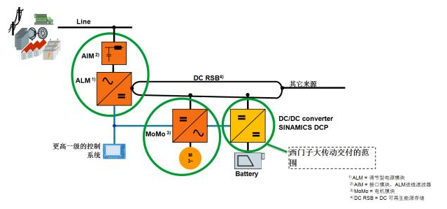
Siemens' SINAMICS DCP products can be widely used in charging piles, electric vehicles, energy storage systems, battery simulation, electric drive ships, peak power absorption, and other occasions where energy conversion is required. It is especially suitable for applications in energy storage and energy saving systems. Its typical application is shown in the figure below, which can be connected to various energy storage media and DC sources. It can also be used as a component of the traditional drive system to improve the energy efficiency of the entire system.
Step-down circuit
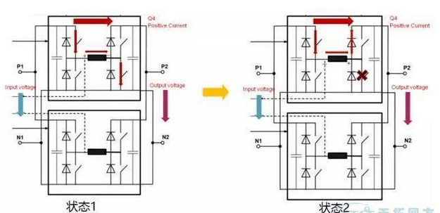
The Boost circuit can achieve a boost in DC voltage. Simply put, it can pump a lower DC voltage to a higher DC voltage. Its working status is shown in the figure below: At this time, the input voltage is lower than the output voltage.

In state 1, as shown in Figure 3, the two IGBTs are turned on, the input side DC power supply is short-circuited through the reactor, and the reactor in the intermediate circuit is charged and stored.
When the DCP is switched from state 1 to state 2, the IGBT of the lower bridge arm which is turned on is turned off. Since the current cannot be changed suddenly, the freewheeling diode corresponding to the upper bridge arm IGBT is turned on. The polarity of the voltage of the reactor is reversed. This is the DC power supply on the input side and the reactor are superimposed in series on the output side in a forward direction, thereby charging the output side and continuously raising the output high voltage. This is the working principle of the BOOST circuit. Because it is a bridge circuit, the other two IGBTs can work to achieve voltage pumping from the output side to the input side for the same reason.
Boost circuit
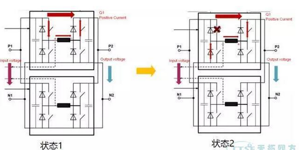
To put it simply, the Buck circuit can ensure the normal operation of the DCP when the DC voltage on the input side is higher than the DC voltage on the output side, and continuously realize the charging process on the output side. Its working status is shown in the figure below: At this time, the input voltage is higher than the output voltage.

In state 1, the two IGBTs are turned on, and the DC power supply on the input side charges and stores the energy of the reactor of the intermediate circuit. At this time, the input DC power is directly charged to the output side through the reactor of the intermediate circuit, and the output voltage is equal to the voltage between the two ends of the reactor. The voltage in series in the forward direction is equal to the DC power supply voltage on the input side. When the DCP is switched from state 1 to state 2, the IGBT of the upper bridge arm that is turned on is turned off. Since the current cannot be changed abruptly, the freewheeling diode corresponding to the lower bridge arm IGBT is turned on. The polarity of the voltage of the reactor is reversed. At this time, the energy stored in the reactor of the intermediate circuit continues to be charged to the output, so that the voltage on the output side can be gradually increased. This is the working principle of the BUCK circuit. Because it is a bridge circuit, the other two IGBTs can work from the output side to the input side to charge the input side in the form of a BUCK circuit.
1. SINAMICS DCP can realize bidirectional DC-DC conversion, real-time boosting and bucking through BUCK/Boost circuit.
2. The overload capacity can reach 150%, which can realize constant voltage control or constant current control.
3. The operating characteristics of a wide voltage range of 0V-800V are beyond the reach of opponents of crystal oscillators.
4. The integrated MPPT (Maximum Power Point Tracking) function can be easily integrated into the solar photovoltaic system.
5. The weak DCP is used for battery charging equipment and can also use the integrated battery charging characteristic curve function.
6. The DCP integrated control unit CUD is equipped with a standard PROFIBUS DP communication interface. It can also be expanded to a PROFINET interface with the accessory CBE20. It can be easily adjusted by using the STARTER software that everyone is very familiar with.
Case studyIn the test bench industry. In the current pure electric vehicle experiment, in order to be able to truly reproduce the state of the road vehicle, the vehicle battery pack is used for the experiment. But here comes the problem. You know the capacity of the battery pack, it will run out in a few hours. It is inconvenient to change the battery pack and charge. Therefore, DCP comes in handy, it can truly simulate the volt-ampere characteristics of a DC battery pack. Therefore, using DCP instead of battery packs to supply power to pure electric vehicles is equivalent to battery packs. In this way, the test data is true, and there is no need to always change the battery. Isn't it convenient?
For another example, when DC/DC conversion is used, this is an electronic transformer, and it has a large capacity. Like DC buses of different voltage levels, if you want to connect them together, use this for voltage transformation to achieve a common DC bus. The common DC bus is often a hybrid system of electric and power generation, and they can use each other to achieve low energy consumption indicators.
Related Links Two-way DC/DC converter circuit Brief introduction to the role of pwm converter What is the technical road of two-way DC/DC power supply?
What is the principle of a bidirectional dc-dc converter
Suizhou simi intelligent technology development co., LTD , https://www.msmvape.com