In the push-pull amplifier circuit, because at least two output tubes are used to amplify the positive and negative half cycles of the signal, it is necessary to design an inverter circuit in the circuit to allocate the appropriate corresponding signal to the power output tube, so as to meet the push-pull amplification The basic working conditions of the circuit. In the inverter circuit of the tube amplifier, there are inverters that use transformers, and those that use bile ducts. For example, we often see screen-inverted split inverters, long tail inverter circuits, etc., but there are certain advantages and disadvantages regardless of which method can be used to reverse the inverter. The use of transformers for inverter circuit design is costly. , And can not use large negative feedback to improve sound quality, few people use it. However, it is difficult for the tube inversion circuit to ensure the consistency of the positive and negative half-cycle division of the signal from low frequency to high frequency. These shortcomings of the inverter circuit make the playback of sound quality an obstacle in this link.
The power output circuit of single-ended amplifier is lower in efficiency than the push-pull amplifier circuit, making the circuit much simpler than the push-pull circuit, using fewer components, and the failure rate is much lower than the push-pull amplifier circuit. Since the single-ended amplifier circuit does not have an inverter circuit, the signal directly reaches the input stage of the final power amplifier tube, so there is no trouble of the inverter circuit. In the push-pull amplifier circuit, the positive and negative half-cycle signals after inversion must be sent to the "up and down" push-pull tubes to perform push-pull amplification at the gate level. Since at least two power tubes are required to coordinate work, this requires each The consistent performance of the amplifier tube amplifier is better, so as to ensure that the waveform after the push-pull amplification is complete and not distorted, but in fact the performance of each pair of push-pull tubes is difficult to ensure the consistency from low frequency to high frequency. The so-called pairing is just pairing within a certain frequency range. If the push-pull amplifier circuit works in the Class B state, there is also the danger of crossover distortion. In the single-ended amplifier circuit, because the positive and negative complete waveforms of the signal are amplified in a power amplifier, and because the single-tube amplifier circuit mostly works in the Class A state, the working point of the Class A amplifier circuit is The middle part of the straight part of the curve is selected, so there is no problem such as crossover distortion. Another comparison is that the amplifier is better than the transistor (relatively speaking). One of the main reasons is that although the transistor machine has done a lot of indicators, the third harmonic distortion is larger than the amplifier, that is, the odd harmonic comparison The second harmonic distortion of the amplifier is larger than that of the transistor, that is, the even-order resonance dynamic wave distortion is greater than that of the transistor, but from the hearing sense, the human ear is more sensitive to odd harmonic distortion, which brings people The impression is a blunt feeling, which is more annoying, but the sub-harmonic distortion brings a soft feeling. The human ear is easier to accept, just like the right amount of condiment, which is also a major factor in the sound of the amplifier.
In terms of push-pull amplifier circuit and single-ended amplifier circuit, the odd-order harmonic distortion of the single-ended amplifier output circuit is lower than that of the push-pull amplifier circuit. The wave is distorted, so it sounds better.
Although the single-ended amplifier circuit is simple and easy to manufacture, the arrangement of components between the circuits is strict, the design is unreasonable, and it is easy to produce hum. The single-ended output transformer is more complicated to produce than the push-pull output transformer. This is because the output transformer of the single-ended amplifier circuit has DC high voltage through the primary stage, which will produce magnetic saturation. Although the push-pull output cattle also has DC high voltage passes, but this phenomenon can be counteracted. Therefore, when the silicon steel sheet is put in, a certain gap and air gap should be left. The size of the air gap depends on the circuit requirements and output power. Because silicon steel has an air gap, the permeability of the entire output cow is greatly reduced, so it is necessary to use a silicon steel sheet with a larger cross-sectional area to produce it. The cost is greater than that of the push-pull output cow at the same output power. some.
The single-ended output amplifier circuit is very popular and sought after by experienced audiophiles because of its simple circuit, good sound quality and extremely low failure rate. Do n’t forget that there are many bile ducts in the world, all of which depend on the fascinating sound played by the design of the single-tube output circuit. For example, the WE300B, Danwang 845, known as the "Prince Charming", and the noble sound quality they reproduce can only exert their maximum potential when they are output at a single end.
These keywords represent critical components and applications within the electrical and industrial sector. Here's how they can be classified:
-
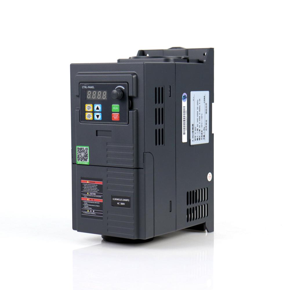
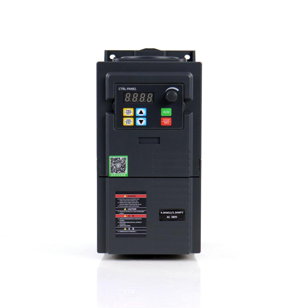
Frequency Converter: A frequency converter is a device that converts the frequency of an alternating current (AC) to match the requirement of a particular electrical device or system. This allows equipment designed for specific frequency to operate in regions where the electrical supply has a different frequency. For example, a frequency converter can be used to allow a device designed for a 60Hz supply to operate in a region with a 50Hz supply.
-
Variable Frequency Drive (VFD): A VFD is a type of motor controller that drives an electric motor by varying the frequency and voltage of its power supply. VFDs have significant applications in industrial systems and machinery, where they allow for precise control of motor speed and torque, leading to increased efficiency and longevity of equipment.
-
Pumps, Fans, Conveyors: These are common applications of motors controlled by VFDs. The variable speed provided by the VFD allows these systems to operate more efficiently and adjust to the specific demands of their task. For instance, a pump's flow can be controlled more accurately, fans can be speed adjusted according to the cooling requirement, and conveyor speed can be precisely managed based on the production line's needs.
-
Phase Motor: A phase motor refers to the type of electric motor, which operates based on the phase of the power supply. The most common types are single-phase motors and three-phase motors. Single-phase motors are usually found in lower power applications like household appliances, while three-phase motors are used in higher power applications, often in industrial settings. These motors can be controlled using VFDs for enhanced performance and efficiency.
These components play significant roles in various industries and are essential for efficient operation in many modern systems. The use of VFDs and phase motors, in particular, has revolutionized the way we control and optimize industrial processes, leading to substantial improvements in energy efficiency and system longevity.


Frequency Converter,Variable Frequency Drive,Pumps Fans Conveyors,Phase Motor
WuXi Spread Electrical Co.,LTD , https://www.vfdspread.com