MPXM2010 pressure measurement and control system and its accuracy improvement method
Pressure measurement and control system is one of the common application modules in embedded applications, and is widely used in various measurement and control systems in modern industry. This article introduces a pressure measurement and control system designed based on low-cost devices such as the MPxM2010 pressure sensor produced by Freescale and the 68HC908QT4 microcontroller.With the hardware cost almost not increasing, the system is increased by matching simple analog circuits and software programming measurement accuracy. In this paper, the numerical calculation of the system before and after the accuracy improvement is compared, which shows that the accuracy of the system has been significantly improved. The method introduced in the article can also be applied to other application environments of A / D conversion, which is of great benefit in reducing the system cost.
Keywords: 68HC908QT4 MPxM2010 silicon piezoresistive sensor A / D conversion accuracy improvement
Introduction
The MPXM2010 device produced by Freescale is a silicon piezoresistive pressure sensor. MPXM20lO has high accuracy, and the output voltage has a good linear relationship with the pressure of the people. This sensor is a monolithic integrated circuit, which integrates a pressure strain gauge and a membrane resistance network, and has a laser fine-tuning module for temperature compensation and offset. The microcontroller 68HC908QT4 is a low-end 8-bit microcontroller. There are 4 8-bit A / D conversion channels and 16-bit PWM module, which can be used for A / D and D / A conversion.
Combining the two chips together can form a practical low-cost pressure measurement and control system. The disadvantage is that its accuracy is lower. If the A / D digits are increased, the cost will be greatly increased. This shortcoming can be compensated by hardware collocation and software programming, that is, without increasing hardware overhead and improving product performance.
1 Design of pressure sensor module
The MPXM2010 device produced by Freescale is a silicon piezoresistive pressure sensor. Its internal principle is shown in Figure 1. MPXM2010 has high accuracy, and the output voltage has a good linear relationship with the input pressure. This sensor is a monolithic integrated circuit, which integrates a pressure strain gauge and a membrane resistance network, and has a laser fine-tuning module for temperature compensation and offset correction.
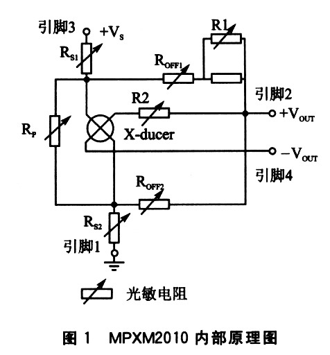
MPXM2010 features are as follows:
◇ The pressure measurement range is O ~ 10 kPa, and the accuracy can reach ± ​​O. 01 kPa;
◇ With temperature compensation function between O ~ 85 ℃;
â—‡ The linear relationship between output signal and pressure is good;
â—‡ The sensor contact surface can choose whether to bring out the nozzle;
â—‡ There is an easy-to-use packaging form of Tape & Reel. The specific sample picture is shown in Figure 2.
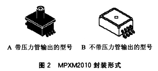
The output signal of MPXM2010 is relatively weak, you need to add an additional MOC2A60 to amplify the small signal, and the DC to AC. This can directly control the motor to cut off or turn on the power. When debugging the module, separate the parts to facilitate debugging. The op amp uses MC33179, and then connects some resistors to output the signal of the pressure sensor, and the size of the output signal can be adjusted by adjusting the resistance. Figures 3 and 4 are the schematic diagram and PCB board diagram of the pressure sensor module design.
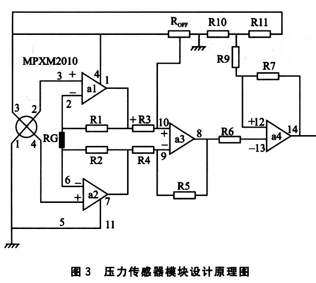
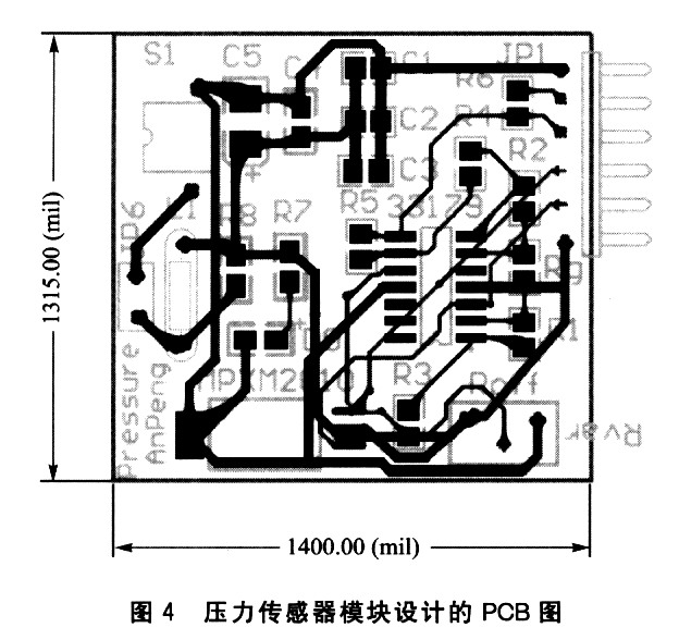
2 Pressure measurement and control system design and accuracy improvement
2.1 Direct-connected pressure measurement and control system
Under normal circumstances, the design can be completed using the 68HC908QT4 A / D module, as long as the output end of the pressure sensor module is connected to the 68HC908QT4 A / D module input. Figure 5 shows the block diagram of the pressure measurement and control system.
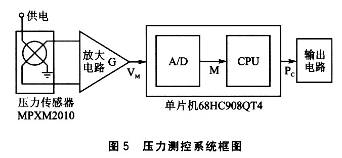
The features of the microcontroller 68HC908QT4 are as follows:
â—‡ 4 KB Flash memory, 128 B RAM memory;
â—‡ 4-channel 8-bit A / D converter, 16-bit PWM module;
â—‡ The price is cheap, the price of each piece of more than 1,000 pieces can be reduced to less than $ 1.
The measuring range of MPXM2010 is 0 ~ 10 kPa, and its output voltage signal is limited to 0 ~ 5 V, then its accuracy is:
S = 5 V ï¼ 10 kPa = 500 mV ï¼ kPa
68HC908QT4 A / D is 8 bits, the voltage limit is 5 V, then its accuracy is:
R = 5 V ï¼ (20-1) bit≈19.61 mV / bit
The pressure accuracy of the entire system is:
R ï¼ S = 19.61 ï¼ 500 kPa / bit = 0.039 22 kPa / bit
If you want to improve the accuracy and raise A / D to 10 digits, the accuracy is:
R / S = O. 03 922X (28-1) / (210-1) kPa / bit = 0.009 776 kPa / bit
After A / D rises to 12 digits, the accuracy is:
R / S = 0.039 22 × (28-1) / (212-1) kPa / bit = 0.002 442 kPa / bit
This can indeed improve the accuracy, but it needs to increase the hardware overhead. Using the 68HC908QT4 PWM module as a D / A converter can improve the accuracy of A / D conversion ingeniously.
2.2 Improved pressure measurement and control system
The reason for the error is that at A / D, the part after the decimal point is rounded off, for example, 176.51 bit will be treated as 176 bit. Solving the problem should also be done manually from here to reduce the error.
The lead-out of the error can be solved by D / A, and the data read in by A / D can be sent out by D / A processing once, and can be obtained by subtracting the original data once. The error cannot be directly sent back to A / D, but it can be amplified and then sent back, and then another A / D in 68HC908QT4 is used to perform the A / D conversion on the amplified error. After the MCU obtains the result, it reduces the same multiple, and The addition of the original A / D transformation results is a more accurate result. In Fig. 6, the whole system can be divided into pressure sensor module, analog part, single chip part and output circuit part. The key to improve accuracy is the design of analog part. As shown in Figure 7. Assume that the amplification factor of the amplifier G is 10. The performance of A / D has not been improved by itself, and the accuracy is still R = 19.61 mV / bit. This value is also the limit value. After 10 times magnification, the original maximum error of 19.6 mV / bit is expanded to 196.1 mV / bit. A / D processes the magnified data, and its capacity is magnified 10 times. When data processing, it will be divided by lO to restore, as a whole, it is as if the precision R is divided by 10, which becomes 1.961 mV / bit.
For example: the error of the initial A / D conversion is 10 mV, and it becomes 100 mV after being amplified. At this time, after the A / D conversion, the error left over for the second time is 100 mV-19.61 mV / bit × 5 bit = 1.95 mV, and then divided by 10 becomes 0.195 mV. The error is greatly reduced, and its limit value is one-tenth of the original accuracy.
The magnification of G can be adjusted by yourself, but it has no practical significance to choose too high to meet the performance of the selected microprocessor and the accuracy of the circuit itself.
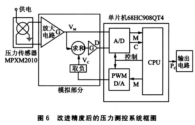
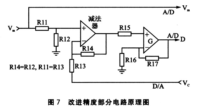
In the circuit shown in Figure 7, Vm, D, and Vc are the same as those shown in Figure 6. The calculated value of D is:
D = (Vm—Vc) × (R14 ï¼ R13) [l + (R17 ï¼ R16)]
The magnification of G is (R14 / R13) [1+ (R17 / R16)].
Conclusion
In the process of product design and development, cost is a very important factor. Clever use of the modules in the microcontroller, assisted by the corresponding simple analog circuit, can greatly improve the utilization efficiency of the chip, and can improve system performance. More use of the things at hand for improvement and re-creation can often achieve more results with less effort.
Gel Battery,Gel Cell Battery,Gel Battery For Car,Gel Type Battery
Power X (Qingdao) Energy Technology Co., Ltd. , https://www.qdpowerxsolar.com