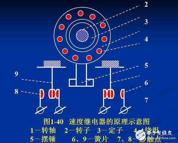
The speed relay is coaxially connected with the controlled motor. When the motor is braking, it will still rotate by inertia and drive the rotor of the speed relay to rotate together. The rotating magnetic field of the rotor induces electromotive force and current in the stator winding of the speed relay, which can be determined by the left-hand rule. At this time, the stator is subjected to the same electromagnetic torque as the rotor turning, causing the stator and the rotor to rotate in the same direction. The bakelite swing rod fixed on the stator also rotates, pushing the reed (moving contact at the end) and the static contact to close (depending on the direction of rotation of the shaft). The static contact acts as a stop again, restricting the bakelite pendulum rod from continuing to rotate. Therefore, when the rotor rotates, the stator can only rotate through a small angle. When the rotor speed is close to zero (less than 100 rpm), the bakelite swing rod returns to its original state, the contact is disconnected, and the reverse braking circuit of the motor is cut off. n The operating speed is generally not less than 300 rpm, and the reset speed is about 100 rpm or less.
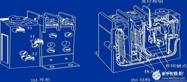
When the motor is overloaded, the current flows through the resistance wire connected in series in the stator circuit to cause excessive heat. The bimetallic plate expands due to heat. Due to the different expansion coefficient, the lower end of the left piece with the larger expansion coefficient bends to the right, and the guide plate pushes the compensation bimetal. The piece makes the push rod rotate around the axis, drives the lever to rotate it around the axis, and disconnects the normally closed contact. The contactor coil is de-energized and the main contact is released, so that the motor is protected from the power supply.
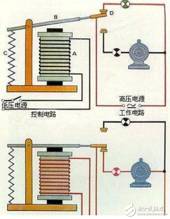
Electromagnetic relays are generally composed of iron cores, coils, armatures, contact reeds, etc. As long as a certain voltage is applied to the two ends of the coil, a certain current will flow through the coil, which will produce electromagnetic effects. Under the action of electromagnetic force, the armature will overcome the pulling force of the return spring and attract to the core, thereby driving the armature. The moving contact and the static contact (normally open contact) are pulled together. When the coil is de-energized, the electromagnetic attraction will also disappear, and the armature will return to its original position under the reaction force of the spring, so that the moving contact and the original static contact (normally closed contact) are attracted. This pulls in and releases, so as to achieve the purpose of conducting and cutting off in the circuit. The "normally open and normally closed" contacts of the relay can be distinguished as follows: the static contact that is in the off state when the relay coil is not energized is called "normally open contact"; the static contact that is in the on state is called It is a "normally closed contact".
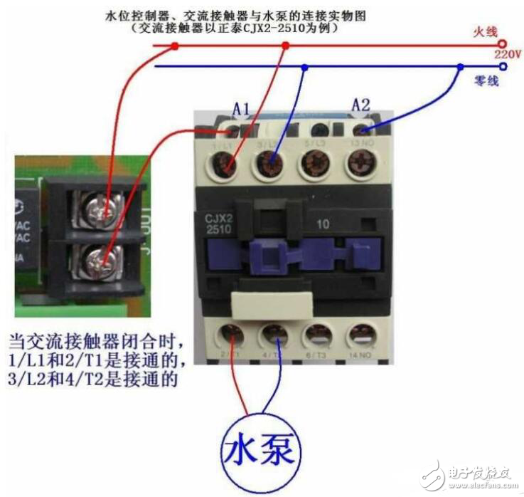
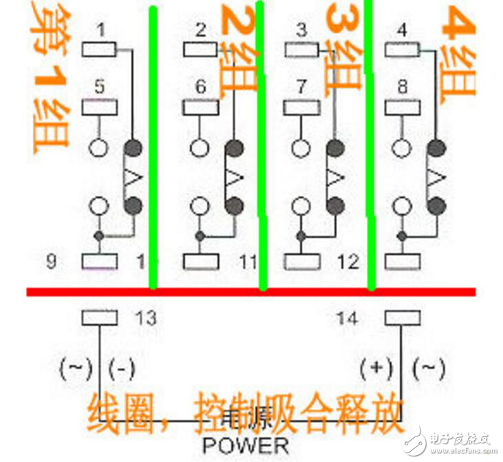
Each intermediate relay is marked with the voltage level and wiring method, generally 13 and 14 are connected to the coil, and the remaining four groups of contacts can be connected according to the label. Among them, 13 and 14 are the coil pins of the relay, which are used to connect to the control power supply. The intermediate relay controls the opening and closing of the contacts by controlling whether the coil is energized or not. 1, 5, 9; 2, 6, 10; 3, 7, 11; 4, 8, 12 are four contacts respectively, of which 1, 2, 3, 4 are contact common terminals, 5, 6, 7, 8 is the normally closed point, and 9, 10, 11, and 12 are the normally open points. The four groups 1, 2, 3, and 4 are totally irrelevant electric shocks. 1 is related to 5 and 9, and 2, 3, 4 and 1 are the same.
Pipeline Oil Contamination Detection Sensor
This decice is installed in the cooling water line of ship and is designed to detect oil in cooling water.This system consists of oil detection pot,capacitive compact switch and control unit.Oil detection pot for separating oil and water has not cock valve for isolating the input and output line.Capacitive Type Oil Detector is installed in oil detection pot for separating oil and water has not cock valve for isolating the input and output line.Capacitive type oil detection pot,detecting oil Isolated form water on the top of oil detection pot.Control unit receive whether it is deteted or not in signal from the capaciteve compact switch and convert point of contact to relay contact.
Pipeline Oil Contamination Detection Sensor,New Ss Oil Pressure Sensor,Oil Pressure Sensor,Ss Oil Pressure Sensor
Taizhou Jiabo Instrument Technology Co., Ltd. , https://www.taizhoujiabo.com