0 Introduction Due to the increasing shortage of petroleum resources and people's awareness of environmental protection, new types of power vehicles are emerging, such as hydrogen fuel vehicles and ethanol fuel vehicles. Among them, environmentally-friendly vehicles powered by electric energy are developing more rapidly. The trolley bus carrying the battery is the most promising public transport. In addition to the advantages of the tram, it also eliminates the advantages of erecting part of the power supply line and plays an extremely important role in beautifying the city. According to the data, in 2008, nearly 800 such "quasi" trolley buses were put into operation in Beijing. However, due to the large number of internal batteries of such large electric vehicles and the supply voltage reaching 500 V, the insulation and leakage treatment technology has always been a major problem for tram developers. At present, the tram power supply system adopts multiple inverter technology, which strictly isolates the low voltage 24 V power supply from the high voltage motor drive part and the large charger part, and installs the discharge iron chain in contact with the earth, so that the leakage problem is very good. solve. However, in sporadic situations, especially in rainy weather conditions, there will still be electric shocks during passengers getting on the train. In view of this, it is necessary to develop a leakage detecting device that measures the voltage between the ground and the wagon in real time.
This article refers to the address: http://
1 Working principle The device is installed inside the tram. The power supply voltage is the low voltage 24 V power supply on the tram (the actual working voltage is 18~36 V). The device itself is equipped with 3 LED indicators, which are the system working power indicator green light and low voltage. Leakage 30 V indicates yellow light and high voltage leakage. The red light is indicated above 70 V. One of the wires is an iron chain lead and the other two are wired to the front panel display system. The system block diagram is shown in Figure 1.
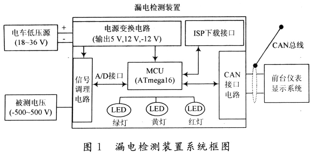
The trolley skin itself is the negative pole of the low-voltage power supply. From the past actual measurement and theoretical analysis, the measured iron chain reaches the total voltage of the internal battery of the tram under the leakage condition, and the voltage between the trolley and the vehicle skin is positive and negative. Therefore, the system fully considers the above situation in the design, and has been processed in the design of the signal conditioning circuit. When the voltage between the measured signal and the wagon is between 30 and 70 V or between -30 and -70 V, the yellow light of the device is bright; when the voltage between the measured signal and the wagon is greater than or equal to 70 V or less than or equal to -70 V The device is lit red when the unit is lit.
2 system circuit design and network protocol The core controller of the system uses ATME's high-performance 8-bit AVR microcontroller ATmega 16, which has 8 single-ended 10-bit ADC acquisition interface; 16 KB system on-chip programmable FLASH, The number of programming reaches tens of thousands of times; 1 KB of on-chip SRAM; 32 programmable I/O interfaces; and high operating speed of 16 MIPS. The device adopts the external expansion CAN controller to realize the communication function with the CAN network system of the whole vehicle.
2.1 Signal Conditioning Circuit This part of the circuit mainly regulates the collected voltage and finally converts it into a voltage range of 0~5 V that the MCU can accept. Since the object to be taken is a positive and negative high voltage signal, the system requires ±± 1 V. The detailed design circuit is shown in Figure 2.
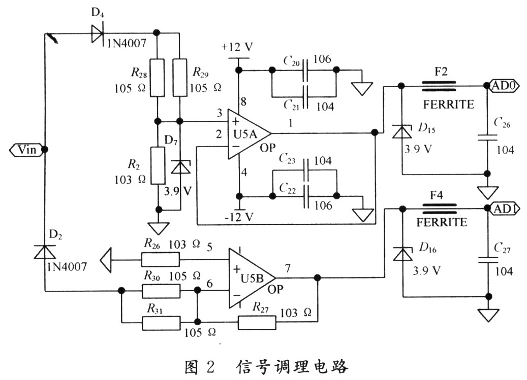
When Vin>0, diode D4 is turned on and D2 is turned off; the voltage value on ADC0 output to the MCU is: ![]()
When Vin<0, diode D2 is turned on and D4 is turned off; the voltage value on ADC1 output to the MCU is: ![]()
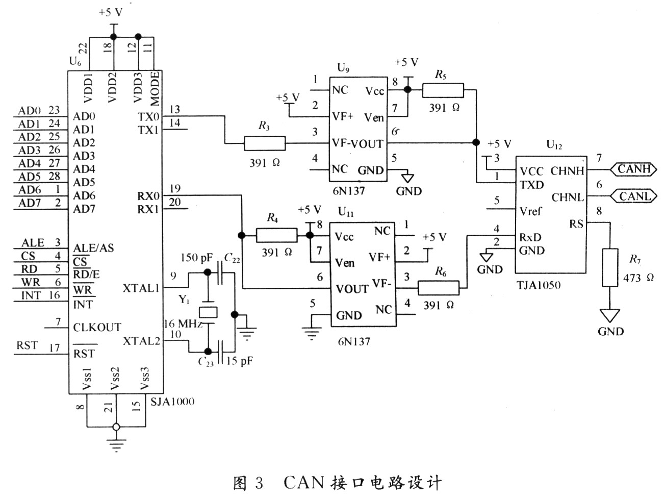
In order to ensure that the voltage value after conditioning meets the ADC interface voltage requirements of the MCU, the voltage regulator is used in the circuit for voltage regulation protection; at the same time, a signal filter circuit is added for smoothing. 2.2 CAN interface circuit and network programming protocol CAN interface circuit uses PHILIPS company's SJA1000 controller and TJA1050 high-performance transceiver. In order to electrically isolate the device from other systems on the tram, such as the battery management system, engine system, and instrument display system, the CAN interface is designed with a high-speed optocoupler 6N137 and a separate isolated 5 V power supply. The 3 000 V required for the isolation specification of tram electrical components. The detailed design is shown in Figure 3.
The CAN 2.0B protocol data unit consists of two parts, an identification code and a data field. The identification code includes priority (P), reserved bit (R), data page (DP), format field (PF), and specific domain ( PS), source address (SA) and data field (DF) seven parts.
SAE J1939 is a protocol for large vehicles based on the CAN 2.0B extended information format. The design is based on this protocol and is compatible with the Beijing Bus's trolleybus electrical control CAN coding protocol, which specifies a communication baud rate of 200 kHz. The identification code consists of 29 bits, which are the status ID and the instruction ID. Defined as: PF=0XFF, PS=0X04, priority=3, address=0X09. The data field consists of 8 bytes and 64 bits, and the data fields of each unit have different definitions.
3 Software routines and applications The software adopts modular and structured programming methods. The software part of the system is mainly composed of the data acquisition module of the single-chip microcomputer and the communication module of the CAN interface; all the codes are written in the C language in the ICC AVR development environment. In this system, the core processor ATmega 16 and the CAN controller use the interrupt trigger method to receive commands and data, and use the polling method to transmit data.
After the system periodically collects the external signal, it sends the data to the bus according to the specified format. At the same time, it advances the message and the flag according to the need and determines whether the transmission is successful. If the CAN controller receives the external command data, it uses the mask filter register to receive the report. The identifier of the text is selectively compared bit by bit with the identifier set in advance when the receiving buffer is initialized, and only the message matching the identifier can enter the receiving buffer and send a signal to the corresponding pin of the MCU, thereby triggering Interrupted.
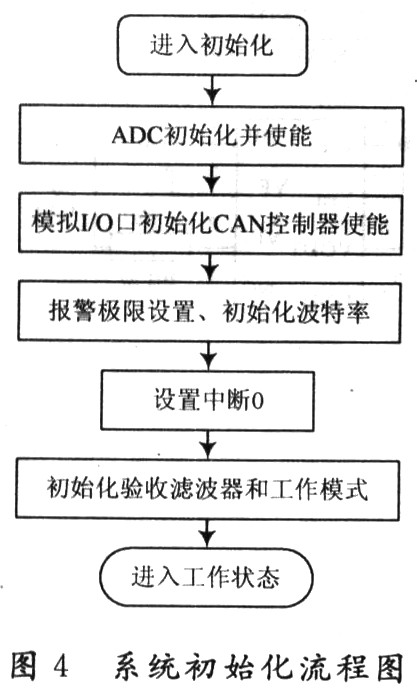
3.1 System Initialization System initialization mainly sets the parameters of the ADC and CAN controller in the system. The main contents include: setting the corresponding two I/O ports to the ADC port, setting the ADC enable and query reading mode. The hardware enables CAN, sets the CAN alarm limit, sets the bus baud rate, sets the interrupt working mode, sets the working mode of the CAN acceptance filter, and sets the working mode of the CAN controller. The initialization process is shown in Figure 4.
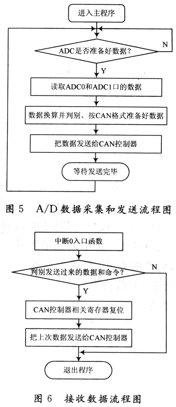
3.3 Receiving Data Program Since the receiving is performed by interrupt, the MCU obtains the interrupt signal and enters the command data to discriminate and the related controller resets the CAN controller. If the data is consistent with the previous specification, the previously prepared data is immediately sent to the CAN controller. The software flow of this function is shown in Figure 6.
4 Conclusion This device can detect the leakage voltage in real time, and send and receive commands and data through CAN bus technology with strong real-time, high reliability and better anti-interference ability. Practice has proved that the device can well monitor the leakage state of the electric train, thereby eliminating the occasional electric shock of passengers getting on the train and improving the safety performance of the whole vehicle.
Industrial energy storage,Clean energy storage,Ensure Power Supply,100kw solar system,energy storage solutions,solar power system,micro grid inverter
EMoreShare International Trade (Suzhou) Co., Ltd , https://www.emoreshare.com