Stepper motors are widely used in the motor industry due to their excellent performance in speed and position control accuracy. For the structure and driving method of the stepper motor, the working principle, and the precautions in the application, we will carry out in-depth analysis.
The stepping motor is a special motor for control. Its rotation is operated step by step at a fixed angle (called "step angle"). It is characterized by no accumulation error (accuracy is 100%), so it is widely used. Used in a variety of open loop control. The operation of the stepping motor is driven by an electronic device. This device is a stepper motor driver. It converts the pulse signal from the control system into the angular displacement of the stepper motor, or: every pulse signal sent by the control system. The stepping motor is rotated by one step angle by the driver, so the speed of the stepping motor is proportional to the frequency of the pulse signal. Therefore, controlling the frequency of the stepping pulse signal can accurately adjust the speed of the motor; controlling the number of stepping pulses can accurately position the motor. The existence of this linear relationship, coupled with the stepper motor only periodic error without cumulative error. It is very simple to control the change with a stepping motor in the control field such as speed and position.
First, the construction of stepper motor (take five-phase stepper motor as an example)
The structure of the stepping motor is shown in the following figure, which is roughly divided into two parts: the stator and the rotor. The rotor consists of a rotor 1, a rotor 2 and a permanent magnet.
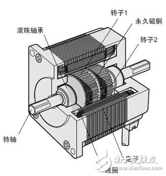
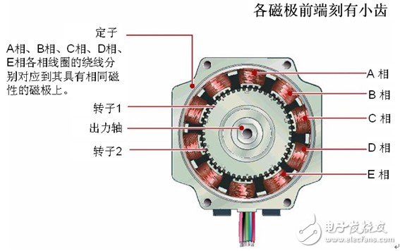
The stator has a small toothed magnetic pole, a total of 10, all with coils. The magnetic poles at the diagonal positions of the coils are connected to each other, and after the current flows, the coils are magnetized to the same polarity. (For example, after a coil is passed through a current, the magnetic pole of the diagonal will be assimilated into an S pole or an N pole.) The two magnetic poles of the diagonal form one phase, and since there are five phases equal to A phase to E, It is therefore called a 5-phase stepper motor.
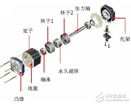
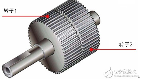
The outer ring of the rotor is composed of 50 small teeth, and the small teeth of the rotor 1 and the rotor 2 are structurally offset from each other by 1/2 pitch. The rotor thus forms 100 small teeth. At present, there are high-resolution models in which the rotor is individually machined to 100 teeth, and the high-resolution rotor has 200 small teeth. Therefore, it can realize the resolution of the ordinary stepping motor half step (the ordinary stepping motor needs to be electrically subdivided in half step).
Second, the working principle of stepper motor
The stator winding produces a vector magnetic field as current flows through the stator windings. The magnetic field causes the rotor to rotate an angle such that the pair of magnetic fields in the rotor coincide with the direction of the magnetic field of the stator. When the stator's vector magnetic field is rotated by an angle. The rotor also turns an angle with the magnetic field. Each time an electrical pulse is input, the motor rotates an angle further. The angular displacement of the output is proportional to the number of pulses input, and the rotational speed is proportional to the pulse frequency. Changing the order in which the windings are energized, the motor will reverse. Therefore, the number of control pulses, the frequency, and the energization sequence of the windings of each phase of the motor can be used to control the rotation of the stepping motor.
Third, the control of stepper motor
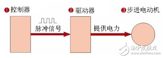
There are three basic drive modes for stepper motor drive: full step, half step, and subdivision. The main difference is the control accuracy of the motor coil current (ie, the excitation mode). Usually, the stepping motor has the characteristics of low frequency vibration, and the balance of the low speed running of the motor can be improved by subdividing and adjusting. Let me introduce you in detail below:
1 , the whole step drive
In the whole step operation, the same stepping motor can be equipped with a full/half step drive or a subdivision drive, but the operation effect is different. The stepper motor driver cyclically energizes the two coils of the two-phase stepper motor according to the pulse/direction command (ie, the coil is charged to set the current). Each pulse of this driving mode will move the motor by a basic step angle, ie 1.80. Degree (200 steps in a circle of a standard two-phase motor).
2 , half step drive
In single-phase excitation, the motor shaft stops at the full step position. After the driver receives the next pulse, if the other phase is excited and remains in the excitation state, the motor shaft will move half a step angle and stop. In the middle of two adjacent full-step positions. The single-phase and then two-phase excitation stepper motor of the two-phase coil is thus cyclically rotated in a half-step manner of 0.90 degrees per pulse. Compared with the whole step mode, the half-step mode has the advantages of double the precision and less vibration during low-speed operation, so the half-step mode is generally used when actually using the full/half-step driver.
3 , subdivision driver
The subdivision drive mode has two advantages of low speed vibration and high positioning accuracy. Subdivision drivers are widely used in stepper applications where low speed operation is sometimes required (ie motor shafts sometimes work below 60 rpm) or positioning accuracy requirements are less than 0.90 degrees.
The basic principle is to perform precise current control on the two coils of the motor according to the steps of sine and cosine, so that the distance of one step angle is divided into several subdivision steps. For example, the driving method of sixteen subdivisions can make the stepping motor of 200 standard steps per revolution reach the running precision of 200*16=3200 steps per revolution (ie 0.1125°).
Fourth, the point of attention in the application
1. Stepper motor is used in low-speed occasions---the speed per minute does not exceed 1000 rpm, (6666PPS at 0.9 degrees), preferably between 1000-3000PPS (0.9 degrees), which can be used to work here through the reduction gear. At this time, the motor has high working efficiency and low noise.
2. It is better not to use the whole step state of the stepping motor, and the vibration is large in the whole step state.
3. The load with large inertia should select the motor with large frame size.
4. When the motor is at a high speed or a large inertia load, it is generally not started at the working speed, but the gradual up frequency is used to speed up, one motor does not lose the step, and the second can reduce the noise and improve the positioning accuracy of the stop.
5. When it is high precision, it should be solved by mechanical deceleration, increasing the speed of the motor, or by using a driver with high subdivision number. It is also possible to use a 5-phase motor, but the whole system is more expensive and has fewer manufacturers.
Five, stepper motor test attention point
According to the national standard GB/T 20638-2006, for the test of stepper motor, we generally need to pay attention to the test of back electromotive force constant, holding torque, winding temperature rise, moment angle characteristic test, pull-out torque, maximum reverse frequency and so on.
For the test of the back electromotive force constant, the back electromotive force constant can be obtained directly on the instrument by the test method of the power analyzer. For the pull-out torque test, for the stepper motor of the large base, the magnetic powder brake and the motor test platform are generally used for testing, and the stepping motor of the small base is tested by a combination of the spring balance and the rope. The MPT motor test system currently provides an overall test plan and test system for stepper motor testing, helping engineers to quickly improve the design of stepper motors.
Watch strap,Headphone Cover,Earbuds Cover,Earphone Cover,Headset Covers
Nantong Boxin Electronic Technology Co., Ltd. , https://www.ntbosen.com