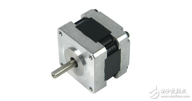
A stepper motor is an actuator that converts electrical pulses into angular displacement. When the stepper driver receives a pulse signal, it drives the stepper motor to rotate a fixed angle (called the "step angle") in a set direction, and its rotation is step by step at a fixed angle. The angular displacement can be controlled by controlling the number of pulses to achieve the purpose of accurate positioning. At the same time, the speed and acceleration of the motor rotation can be controlled by controlling the pulse frequency, thereby achieving the purpose of speed regulation. The stepping motor can be used as a special motor for control, and it is widely used in various open-loop control because it has no accumulation error (100% accuracy).
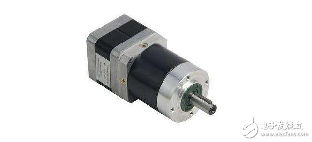
More commonly used stepper motors include reactive stepper motors (VR), permanent magnet stepper motors (PM), hybrid stepper motors (HB), and single-phase stepper motors.
The permanent magnet stepping motor is generally two-phase, with small torque and volume, and the step angle is generally 7.5 degrees or 15 degrees;
The reactive stepping motor is generally three-phase, and can realize a large torque output. The step angle is generally 1.5 degrees, but the noise and vibration are large. The rotor of the reactive stepping motor is made of soft magnetic material, and the multi-phase excitation winding is arranged on the stator, and the torque is generated by the change of the magnetic permeability.
Hybrid stepper motors are a combination of permanent magnet and reactive. It is divided into two phases and five phases: the two-phase step angle is generally 1.8 degrees and the five-phase step angle is generally 0.72 degrees. This stepper motor is the most widely used and is the stepper motor selected for this subdivision drive scheme.
The structure and principle of stepper motorThe stepping motor is a synchronous motor. Its structure is the same as that of other motors. It consists of a stator and a rotor. The stator is an exciting magnetic field. The excitation magnetic field is pulsed, that is, the magnetic field is rotated step by step at a certain frequency, and the rotor is step by step with the magnetic field. go ahead. Stepper motors are mainly reactive, electromagnetic, and permanent magnets. Let's take the reactive stepping motor as an example to discuss its working principle:
The stepper motor consists of a rotor and a stator. Both the rotor and the stator are stacked from toothed silicon steel sheets. The winding on the stator is divided into several phases, and each phase has pole teeth on the magnetic pole. When a certain phase stator winding is excited by a DC voltage, the rotor is attracted, the teeth on the rotor are aligned with the teeth of the phase stator, the rotor is rotated at a certain angle, and the stator winding is alternately excited to rotate continuously, so that the rotor continuously rotates.
The stator of the stepping motor can be made into three, four, five, six phases or even eight phases, and the phase windings can be arranged radially on the stator or in the axial direction of the stator.
The following FLASH is an animated demonstration of the working principle of the stepper motor. The selected example is a sectional view of a single stator radial split-phase reaction stepper motor. There are 40 teeth evenly distributed on the rotor, no windings. A, B, C Three-phase stator has two poles per phase, and there are 5 teeth on each pole. The angle between the teeth is 9°. If the A phase is energized, the rotor teeth are aligned with the A phase pole teeth. At this time, the stator teeth are not aligned with the rotor tooth center line at the B phase poles, but the rotor tooth center line is 1/3 behind the stator tooth center line counterclockwise. The pitch is 3°. In phase C, the rotor teeth lead 6°. Therefore, when the energized state changes from phase A to phase B, the rotor rotates 3° clockwise, and phase C energizes and then turns 3°. Step angle is

Double-shot energization, that is, energized in the order of A-AB-B-BC-C-CA-A..., the step angle is

Generally speaking

Where: m - the number of winding phases;
z——Rotor tooth number, single shot power supply kp=1, double shot power supply kp=2. If the power is applied in the opposite direction as described above, the stepper motor will rotate counterclockwise.
Figure 1 shows a five-phase five-stator axial phase-separated reactive stepper motor. The stator and rotor are divided into 5 sections and arranged in an axial direction. There are 16 teeth on it, so the pitch is 22.5°, and the pitches of the stators of each phase are radially shifted by 1/5 teeth from each other (it can also be radially shifted from the five-stage rotor by 1/5 pitch). If you press the five-phase five-shot power of ABCDEA..., the step angle is

If the ten-shot is energized according to AB-ABC-BC-BCD-CD-CDE-DE-DEA-EA-EAB-AB..., the step angle is 2.25°.
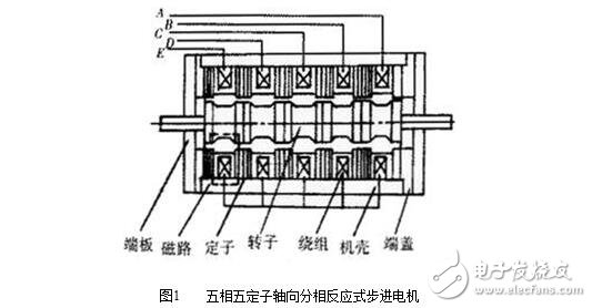
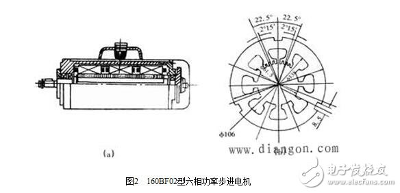
Fig. 2(a) shows a 160BF02 type six-phase power stepping motor. The rotor of the motor has 40 teeth and is not segmented from silicon steel sheets. The step angle can be 1.5° or 0.75°. The stator of the motor is composed of three segments of silicon steel sheet as shown in (b), each segment has 8 magnetic poles, the single pole belongs to the same phase, the double pole belongs to the other phase, and the tooth angle of the pole teeth is also 360°/ 40=9°, the pole teeth of the two-phase magnetic poles on each segment are staggered by 4.5° from each other. When the three-stage stator is installed in the casing, the mark grooves on the three sections are radially shifted by 120° from each other, so that the three uniform cloth key grooves on the three sections are aligned, and are fixed by keys in the key groove. After this assembly, the pole teeth between the segments are staggered by 1.5°. If the two phases of the first segment are A and D phases, the second segment is the B and E phases, and the third segment is the C and F phases. The power stepping motor has a large output torque and a large current on the winding. The structure adopts a combination of radial and axial phase separation, small radial size, small inertia, good heat dissipation, and no magnetic leakage.
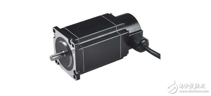
Inherent step angle of the motor:
It represents the angle at which the motor rotates each time the control system sends a step pulse signal. The motor is given a step angle value when it leaves the factory. For example, the 86BYG250A motor gives a value of 0.9°/1.8° (0.9° for half-step operation and 1.8° for full-step operation). This step angle It can be called 'the inherent step angle of the motor', it is not necessarily the true step angle of the actual working of the motor, and the true step angle is related to the drive.
The number of phases of the stepper motor:
It refers to the number of coil groups inside the motor. Currently, two-phase, three-phase, four-phase, five-phase stepping motors are commonly used. The number of phases of the motor is different, and the step angle is also different. Generally, the step angle of the two-phase motor is 0.9°/1.8°, the three-phase is 0.75°/1.5°, and the five-phase is 0.36°/0.72°. When there is no subdivision driver, the user mainly chooses the stepping motor with different phase numbers to meet the requirements of the step angle. If you use a subdivision drive, the 'phase number' will become meaningless, and the user can change the step angle by simply changing the number of subdivisions on the drive.
Holding torque (HOLDING TORQUE):
It refers to the moment that the stator locks the rotor when the stepper motor is energized but does not rotate. It is one of the most important parameters of a stepper motor. Usually, the torque of the stepper motor at low speed is close to the holding torque. Since the output torque of the stepping motor is continuously attenuated as the speed increases, the output power also changes with the increase of the speed, so the holding torque becomes one of the most important parameters for measuring the stepping motor. For example, when people say that a 2N.m stepper motor, unless otherwise specified, is a stepper motor that maintains a torque of 2N.m.
DETENT TORQUE:
It refers to the moment that the stator locks the rotor when the stepper motor is not energized. DETENT TORQUE does not have a unified translation method in China, which is easy to misunderstand. Because the rotor of reactive stepping motor is not permanent magnet material, it does not have DETENT TORQUE.
(1) Even with the same stepper motor, the torque frequency characteristics are quite different when using different drive schemes.
(2) When the stepping motor is in operation, the pulse signal is alternately applied to each phase winding in a certain order (the ring winding in the driver controls the winding to be powered off and on).
(3) Stepper motor is different from other motors, its nominal rated voltage and rated current are only reference values; and because the stepper motor is powered by pulse, the power supply voltage is its highest voltage, not the average voltage, so stepping The motor can operate beyond its rated range. However, the selection should not deviate too far from the rated value.
(4) There is no accumulation error of the stepping motor: the accuracy of the general stepping motor is three to five percent of the actual step angle, and does not accumulate.
(5) The maximum temperature allowed by the appearance of the stepping motor: If the temperature of the stepping motor is too high, the magnetic material of the motor will be demagnetized first, which will cause the torque to drop and even lose the step. Therefore, the maximum temperature allowed by the motor surface should depend on the magnetic material of different motors. Demagnetization point; in general, the demagnetization point of magnetic materials is above 130 degrees Celsius, and some even up to 200 degrees Celsius, so the external temperature of the stepper motor is completely normal at 80-90 degrees Celsius.
(6) The torque of the stepping motor will decrease with the increase of the speed: when the stepping motor rotates, the inductance of each phase winding of the motor will form a back electromotive force; the higher the frequency, the larger the back electromotive force. Under its action, the motor decreases with increasing frequency (or speed), resulting in a drop in torque.
(7) The stepping motor can run normally at low speed, but if it is higher than a certain frequency, it cannot be started, accompanied by howling. The stepping motor has a technical parameter: the no-load starting frequency, that is, the pulse frequency that the stepping motor can start normally under no-load conditions. If the pulse frequency is higher than this value, the motor cannot start normally, and lost or blocked may occur. In the case of load, the starting frequency should be lower. If the motor is to be rotated at a high speed, the pulse frequency should have an acceleration process, that is, the starting frequency is low, and then rise to the desired high frequency at a certain acceleration (the motor speed rises from a low speed to a high speed)
(8) The power supply voltage of the hybrid stepping motor driver is generally a wide range (for example, the power supply voltage of the IM483 is 12 to 48 VDC), and the power supply voltage is usually selected according to the operating speed and response requirements of the motor. If the motor has a higher operating speed or a faster response, the voltage is also higher, but note that the ripple of the supply voltage cannot exceed the maximum input voltage of the drive, otherwise the drive may be damaged.
(9) The power supply current is generally determined based on the output phase current I of the driver. If a linear power supply is used, the power supply current can generally take 1.1 to 1.3 times of I; if a switching power supply is used, the power supply current can generally take 1.5 to 2.0 times of I.
(10) When the offline signal FREE is at a low level, the current output from the driver to the motor is cut off, and the motor rotor is in a free state (offline state). In some automation equipment, if the motor shaft (manual mode) is required to be directly powered while the drive is uninterrupted, the FREE signal can be set low, the motor can be taken offline, and manually operated or adjusted. After manual completion, set the FREE signal high to continue automatic control.
(11) Adjust the direction of rotation of the two-phase stepper motor after power-on in a simple way. Simply swap the A+ and A- (or B+ and B-) wires of the motor and the driver.
(12) The four-phase hybrid stepping motor is generally driven by a two-phase stepping driver. Therefore, the four-phase motor can be connected to two phases by series connection or parallel connection. The series connection method is generally used in the case where the motor speed is low. In this case, the required output current of the driver is 0.7 times of the motor phase current, so the motor generates less heat; and the connection method is generally used in the case where the motor speed is high (also called high speed connection). Method), the required driver output current is 1.4 times of the motor phase current, so the stepper motor generates a large amount of heat.
Construction,Building, Nail,Strip Nail
Zhejiang Best Nail Industrial Co., Ltd. , https://www.beststaple.com