PLL (Phase Locked Loop): It is a phase-locked loop or a phase-locked loop. It is used to uniformly integrate the clock signal to make the high-frequency device work normally, such as accessing data in memory. The PLL is used in feedback techniques in the oscillator. Many electronic devices work properly and usually require an external input signal to be synchronized with the internal oscillating signal. The general crystal oscillator can't do very high frequency due to process and cost. When high frequency application is needed, there is a corresponding device VCO, which is converted into high frequency, but it is unstable, so the phase-locked loop can be used. A stable and high frequency time pulse signal is achieved.
The meaning of phase lock is the automatic control of phase synchronization. The closed loop system that can complete the phase synchronization of two electrical signals is called phase-locked loop, which is called PLL. It is widely used in technical fields such as broadcast communication, frequency synthesis, automatic control and clock synchronization.
A typical phase-locked loop (PLL) system consists of three basic circuits: phase detector (PD), voltage regulator (VCO) and low-pass filter (LPF).
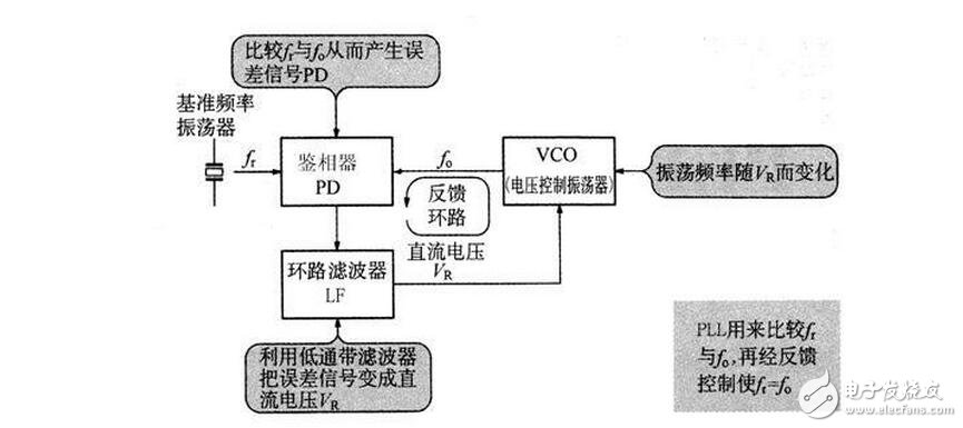
Phase-locked loop capture and tracking process
When the phase-locked loop starts working, its initial state is generally in an unlocked state. Since there is a phase difference between the two signals input to the phase detector, the phase detector will output an error voltage to change the voltage-controlled oscillation. The oscillation frequency of the device is made consistent with the reference signal. The process of locking the phase-locked loop from loss of lock to locking is known as the capture process. The maximum frequency range or maximum natural frequency band that the system can capture is called the capture band or capture range.
When the phase-locked loop is locked, the input signal or the voltage-controlled oscillator frequency changes for some reason, and the loop can be quickly adjusted by its own feedback. The result is that the output frequency and phase of the VCO are locked to the reference signal parameters, thereby maintaining loop lock. This process is called the loop tracking process. The maximum frequency range or maximum natural frequency band that the system can keep tracked is called the sync band or sync range, or the lock range.
The capture process and the tracking process are two different automatic adjustment processes for the phase-locked loop.
It can be seen that the automatic frequency control (AFC) circuit has a fixed frequency difference in the locked state. In the phase-locked loop control (PLL) circuit, there is a fixed phase difference in the locked state. Although there is a phase difference in the phase-locked loop, there is no frequency difference between it and the reference signal, that is, the output frequency is equal to the input frequency. This also shows that frequency control by phase-locked loop can achieve error-free frequency tracking. The effect is far superior to the automatic frequency control circuit.
one. Phase detector (PD)
The phase detector is a key unit circuit in the phase-locked loop. It is responsible for phase comparison of the two input signals and sending the comparison result from the output. There are many types of circuit detectors, and the three most commonly used ones are the following.
(1) Analog multiplier phase detector, which is often used in phase-locked loop circuits where both input signals of the phase detector are sinusoidal.
(2) XOR gate detector, this phase detector is suitable for phase-locked loop circuits where both input signals are square wave signals, so XOR gate detectors are often used in digital circuit phase-locked loops.
(3) Edge-triggered digital phase detector, this phase detector is also a digital circuit type phase detector, which requires less stringent input signals, and can be square wave or rectangular pulse wave. This circuit is often used for high voltage. In the frequency digital phase-locked loop.
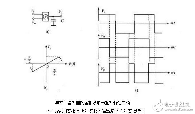
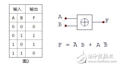
1. The logical truth value of the XOR gate of the XOR gate detector is shown in Table 1, and Figure 2 is a logical symbol diagram.
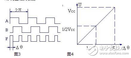
It can be seen from Table 1 that if the input terminals A and B respectively send a signal waveform with a duty ratio of 50%, when there is a phase difference Dθ between the two, the duty ratio of the waveform of the output terminal F is related to Δθ, as shown in FIG. . Smoothing the F output waveform through the integrator, the integrator outputs the average of the waveform, which is also related to Δθ, so that we can use the XOR gate to perform phase-to-voltage conversion to form a phase detection circuit. Then the average value (DC component) after integration by the integrator is:
U = Vdd * Δ θ/π (1)
Different Δθ have different DC components Vd. The relationship between Δθ and V can be described using FIG. As can be seen from the figure, the two have a simple linear relationship:
Ud = Kd *Δθ (2)
Kd is the phase sensitivity
2. As mentioned before the edge-triggered phase detector, the XOR gate phase comparator requires two signals to be compared to have a 50% duty cycle, which brings some inconvenience to the application. The edge-triggered phase detector compares the signal by comparing the upper edge (or lower edge) of the two input signals, and does not require the duty cycle of the input signal.
two. Voltage controlled oscillator (VCO)
The voltage controlled oscillator is an oscillator whose oscillation frequency ω0 is controlled by the control voltage UF(t), that is, a voltage-frequency converter. The characteristics of the VCO can be expressed by a relationship between the instantaneous frequency ω0(t) and the control voltage UF(t). When no control voltage is applied (but it cannot be considered that the control DC voltage is 0, because the voltage at the control terminal should be the superposition of the DC voltage and the control voltage), the oscillation frequency of the VCO is called the free oscillation frequency ωom, or the center frequency, which is linear in the VCO. Within the control range, its instantaneous angular frequency can be expressed as:
Ωo(t)= ωom + K0 UF(t)
Where, K0 - the slope of the VCO control characteristic curve, often referred to as the control sensitivity of the VCO, or voltage control sensitivity.
The voltage controlled oscillator (VCO) is the controlled object of the phase locked loop (PLL). The voltage controlled oscillator is a voltage-to-frequency converter that acts as a frequency-tunable oscillator in the loop, and its oscillation frequency should vary linearly with the input control voltage. The signal output by it can be divided into two categories: sine wave voltage controlled oscillator and non-sinusoidal voltage controlled oscillator according to different requirements of phase locked loop.
The sinusoidal voltage controlled oscillator is generally composed of an LC point oscillator and a varactor. It works exactly the same as the calculation formula and the capacitor three-point sine wave oscillator. Since the sinusoidal VCO is limited by the variation range of the varactor diode capacitance, the variation range of the general oscillation frequency is not too large. There are many types of non-sinusoidal voltage-controlled oscillators. Because of its large frequency variation range and good control linearity, it is widely used. Several circuits commonly used in such voltage controlled oscillators include an emitter timing voltage controlled multivibrator, an integral Schmidt voltage controlled oscillator, and a digital gate voltage controlled oscillator.
The figure shows two square wave voltage controlled oscillator circuits.
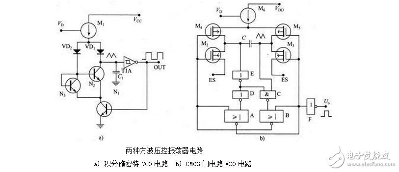
three. Loop filter
Only the passive proportional integral filter is discussed here. Its transfer function is:

Where: Ï„1 = R1 C
Τ2 = R2 C
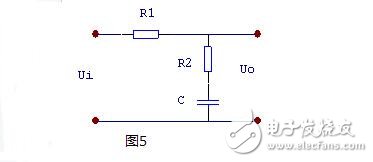
The picture shows three commonly used loop filter circuits. As can be seen from the figure, the complexity of the three circuits is different. The first simple RC filter uses the fewest components and the simplest circuit. The active proportional-integral filter uses the most components and the circuit is more complicated.
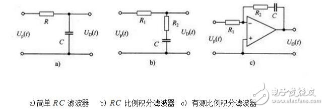
However, from the perspective of filtering effect, the active proportional integral filter has the best filtering effect, the simple RC filter has the worst filtering effect, and the filtering effect of the RC proportional integral filter is between the two. When designing a circuit, different loop filters can be selected according to the requirements of the phase-locked loop.
four. Phase model and transfer function of phase-locked loop
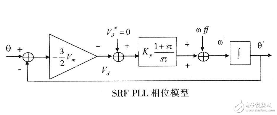
The picture shows the phase model of the phase-locked loop. One thing to note is that the phase-locked loop is a phase feedback system in which the phase is flowing, not the voltage. Therefore, studying the phase model of the phase-locked loop gives the complete performance of the loop.
As can be seen from Figure 6:
(1) When the A point is disconnected, the open-loop phase transfer function of the phase-locked loop is

(2) The phase transfer function when the loop is closed is

(3) The phase error transfer function when the loop is closed is

When the loop filter uses a passive proportional-integral filter, it can be derived by:

In the middle


Also available:

Ωn is called the natural frequency or natural angular frequency of the system;
x is called the damping coefficient of the system.
It should be noted that ω in the above discussion refers to the angular frequency of the input signal phase, rather than the angular frequency of the input signal itself. If the input signal is a frequency modulated signal, then ω refers to the angular frequency of the modulated signal rather than the angular frequency of the carrier.
Fives. Synchronization and capture of phase-locked loops
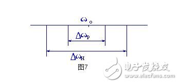
The output frequency of the phase-locked loop (or the frequency of the VCO) ωo can track the operating state of the input frequency ωi, called the synchronous state. In the synchronous state, there is always ωo = ωi. Under the condition that the phase locked loop remains synchronized, the maximum variation range of the input frequency ωi is called the synchronous bandwidth and is represented by DωH. Beyond this range, the loop loses lock.
When the lock is lost, ωo≠ωi, if you try to change ωi from two directions, make ωi move closer to ωo, and then make Δωo =(ωi-ωo)↓. When Δωo is small enough, the loop enters from loss of lock. Locked state. This frequency range that causes the PLL to undergo frequency pulling and eventually causes the lock to enter is called the capture band Δωp. The timing of the synchronization band ΔωH, the capture band Δωp and the VCO center frequency ωo is as shown in Fig. 7.
Copper Flex Membrane Switch panels can be produced using polyester or polyimide (Kapton) as the base material, depending on your interface requirements. A very thin sheet of copper is laminated to the flexible film substrate then chemically etched away, leaving copper traces. The etching process is not environmentally friendly due to the chemicals used, and is also more expensive than screen printing the silver traces used in Silver Flex Membrane Switches. Copper Flex switches can be constructed as:
Single-sided – conductive traces one side of the film substrate
Double-sided – conductive traces both sides of the film substrate
Multi-Layer flex – a laminated [sandwich" of numerous layers with conductive traces
Rigid-Flex – a laminated combination of a Copper Flex switch with a rigid FR4 PCB membrane switch
Copper Flex Membrane Switches,Anti Light Leakage Membrane Switch,Fpc Light Membrane Switch,Rim Embossed Membrane Switch
Dongguan Nanhuang Industry Co., Ltd , https://www.soushine-nanhuang.com