Serial communication interface standards have been used and developed, and there are currently several. But they are all based on the improvement of the RS-232 standard. Therefore, we will mainly discuss RS-232C.
Before discussing the content of the RS-232C interface standard, two points will be explained. First, the RS-232-C standard was originally developed by the remote communication connection data terminal equipment DTE (Data Terminal Equipment) and the data communication equipment DCE (Data Communica TIon Equipment). Therefore, the development of this standard does not consider the application requirements of computer systems. But now it is widely borrowed for the near-end connection standard between computers (more precisely, computer interfaces) and terminals or peripherals. Obviously, some of the provisions of this standard are inconsistent and even contradictory with computer systems. With this understanding of the background, it is not difficult to understand where the RS-232C standard is incompatible with the computer.
Secondly, the "send" and "receive" mentioned in the RS-232C standard are all based on the DTE position, rather than standing in the position of the DCE. In computer systems, where information is often transferred between the CPU and the I/O device, both are DTEs, so both parties can send and receive.
The RS-323C standard is a communication protocol announced in 1969 by the United States EIA (Electronic Industries Federation) and BELL and other companies. It is suitable for communication with data transmission rates ranging from 0 to 20000 b/s. This standard specifies the issues related to serial communication interfaces, such as signal line functions and electrical characteristics. Since the peripheral equipment manufacturers all produce communication equipment compatible with the RS-232C standard, it is widely used as a standard in microcomputer communication interfaces.
First, RS-232-CThe full name of the RS-232C standard (protocol) is the EIA-RS-232C standard, in which EIA (Electronic Industry AssociaTIon) represents the American Electronics Industry Association, RS (ecommeded standard) represents the recommended standard, 232 is the identification number, and C represents the latest RS232. Modified (1969), before this, there are RS232B, RS232A. . It specifies the connection cable and mechanical, electrical characteristics, signal functions and transmission processes. Common physical standards are also EIA? RS-232-C, EIA? RS-422-A, EIA? RS-423A, EIA? RS-485. Only EIA is introduced here? RS-232-C (referred to as 232, RS232). For example, the COM1 and COM2 interfaces currently on IBM PCs are RS-232C interfaces.
Electrical characteristicsThe EIA-RS-232C specifies electrical characteristics, logic levels, and various signal line functions.
On TxD and RxD: Logic 1 (MARK) = -3V to -15V
Logic 0 (SPACE) = +3 ~ +15V
On control lines such as RTS, CTS, DSR, DTR and DCD:
Signal valid (on, ON state, positive voltage) = +3V ~ +15V
Invalid signal (open, OFF state, negative voltage) = -3V to -15V
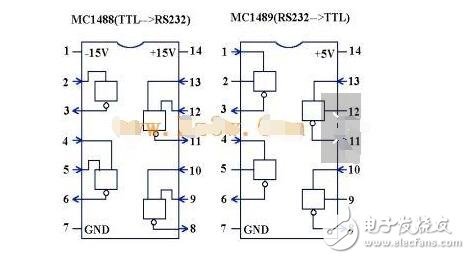
figure 1
The above provisions describe the definition of logic levels in the RS-323C standard. For data (information code): the level of logic "1" (signature) is lower than -3V, the level of logic "0" (space number) is +3V; for control signal; ON state (ON) The effective level of the signal is higher than +3V, and the off state (OFF) means that the level of the signal is invalid is lower than -3V, that is, when the absolute value of the transmission level is greater than 3V, the circuit can effectively check out, between - The voltage between 3 and +3V is meaningless. The voltage below -15V or higher than +15V is considered meaningless. Therefore, the actual level should be between ± (3 ~ 15) V.
EIA-RS-232C and TTL conversion: EIA-RS-232C uses positive and negative voltages to indicate the logic state, which is different from the specification that the TTL indicates the logic state at high and low levels. Therefore, in order to be able to interface with a computer interface or terminal TTL device, the level and logic relationship must be changed between the EIA-RS-232C and the TTL circuit. The method of implementing this transformation can be a discrete component or an integrated circuit chip. At present, integrated circuit conversion devices are widely used, such as MC1488 and SN75150 chips, which can convert TTL level to EIA level, while MC1489 and SN75154 can realize EIA level to TTL level conversion. The MAX232 chip performs TTLâ†â†’EIA bidirectional level shifting. Figure 1 shows the internal structure and pins of the 1488 and 1489. Pins (2), (4, 5), (9, 10), and (12, 13) of the MC1488 are connected to the TTL input. Pins 3, 6, 8, and 11 are terminated with EIA-RS-232C. The 1, 4, 10, and 13 pins of the MC1498 are connected to the EIA input, while the 3, 6, 8, and 11 pins are connected to the TTL output. The specific connection method is shown in Figure 2. On the left side of the figure is the main chip UART in the serial interface circuit of the microcomputer. It is a TTL device, and the EIA-RS-232C connector on the right requires EIA high voltage. Therefore, all output and input signals of RS-232C must pass through MC1488 and MC1498 converters respectively, and then level-converted before they can be sent to the connector or sent from the connector.
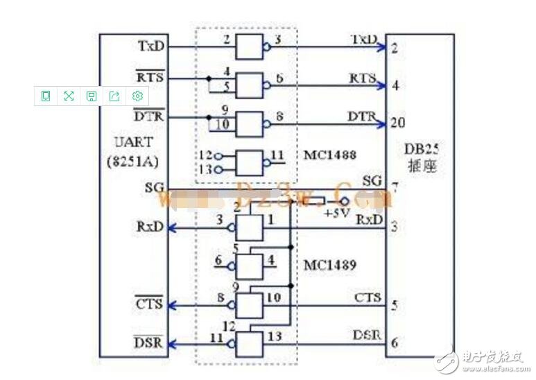
figure 2
2, the mechanical characteristics of the connectorConnector: Since RS-232C does not define the physical characteristics of the connector, various types of connectors of DB-25, DB-15 and DB-9 have appeared, and the definition of the pins is also different. The two connectors are described below.
(1) DB-25:
PC and XT machines use DB-25 connectors. The DB-25 connector defines 25 signal lines divided into 4 groups:
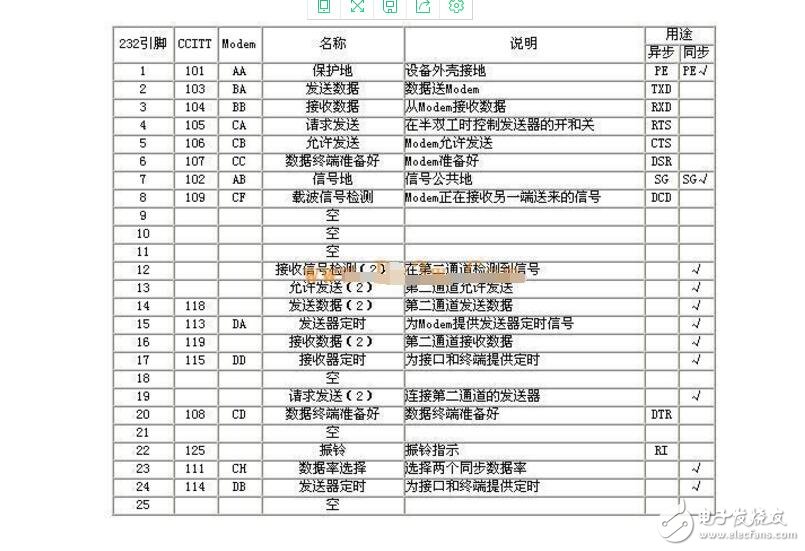
1 9 voltage signals for asynchronous communication (including signal ground SG) 2,3,4,5,6,7,8,20,22
12 mA current loop signals (12, 13, 14, 15, 16, 17, 19, 23, 24)
3 empty 6 (9,10,11,18,21,25)
4 protective ground (PE), as the equipment ground (1 pin)
The outline and signal line assignment of the DB-25 connector is shown in Figure 3. Note that the 20mA current loop signal is only available on IBM PCs and IBM PC/XT machines, and is not supported on AT machines and beyond.
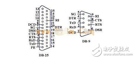
image 3
(2) DB-9 connector
In the AT machine and later, the 20mA current loop interface is not supported, and the DB-9 connector is used as a connector for providing a multi-function I/O card or two serial interfaces of COM1 and COM2 on the motherboard. It only provides 9 signals for asynchronous communication. The pin assignment of the DB-25 type connector is completely different from the DB-25 type pin signal. Therefore, if you connect to a DCE device that is mated to a DB-25 connector, you must use a special cable.
Cable length: The maximum physical distance to which the RS-232C is directly connected is 15m (50 feet) at communication rates below 20kb/s.
Maximum direct transmission distance specification: The RS-232C standard stipulates that if MODEM is not used, the maximum transmission distance between DTE and DCE is 15m (50 feet) when the symbol distortion is less than 4%. It can be seen that this maximum distance is given on the premise that the symbol distortion is less than 4%. In order to ensure that the symbol distortion is less than 4%, the interface standard specifies in the electrical characteristics that the load capacitance of the driver should be less than 2500pF.
3, RS-232C interface signalThe RS-232C standard interface has 25 lines, 4 data lines, 11 control lines, 3 timing lines, 7 spare and undefined lines, and only 9 are commonly used. They are
(1) Contact control signal line:
Data set ready (DSR) - Active (ON) state, indicating that the MODEM is in a usable state.
Data set ready (DTR) - Active (ON) state, indicating that the data terminal is available.
These two signals are sometimes connected to the power supply and are effective as soon as they are powered up. The two device status signals are valid, only indicating that the device itself is available, and does not indicate that the communication link can start communication. Whether or not communication can be started is determined by the following control signals.
Request to send-RTS - Used to indicate that the DTE requests the DCE to send data, that is, when the terminal wants to send data, make the signal valid (ON state) and request transmission to the MODEM. It is used to control whether the MODEM is going to enter the transmission state.
Clear to send (CTS) - used to indicate that the DCE is ready to receive data sent by the DTE, which is a response signal to the request to send signal RTS. When the MODEM is ready to receive the data transmitted from the terminal and transmit it forward, the signal is validated, and the terminal is notified to start transmitting data along the transmission data line TxD.
The pair of RTS/CTS request response contact signals is used for switching between the transmission mode and the reception mode in the half-duplex MODEM system. Switching between the transmission mode and the reception mode in a full-duplex system. In a full-duplex system, because the bidirectional channel is configured, the RTS/CTS contact signal is not required to make it high.
Received Line DetecTIon-RLSD - Used to indicate that the DCE is connected to the communication link, informing the DTE that it is ready to receive data. When the local MODEM receives the carrier signal sent by the MODEM at the other end of the communication link (remote), the RLSD signal is valid, the terminal is notified to prepare for reception, and the received carrier signal is demodulated into digital two data by the MODEM. Then, it is sent to the terminal along the receiving data line RxD. This line is also called the Data Carrier dectecTIon-DCD line.
Ringing-RI—When the MODEM receives the ringing call signal from the switching station, it makes the signal valid (ON state), notifying the terminal that it has been called.
(2) Data transmission and reception lines:
Transmitted data-TxD - Sends serial data to the MODEM via the TxD terminal, (DTE→DCE).
Received data (RxD) - Receives serial data from the MODEM via the RxD line terminal (DCE → DTE).
(3) Ground wire
There are two lines SG, PG - signal ground and protective ground signal line, no direction.
When the above control signal lines are valid and when they are invalid, the order of the interface signals is transmitted. For example, a transfer operation between DTE and DCE can only be performed when both DSR and DTR are in the active (ON) state. If the DTE wants to transmit data, the DTR line is set to the active (ON) state in advance, and the serial data can be transmitted on the TxD line after the CTS line receives the answer of the valid (ON) state. This sequence of rules is particularly useful for half-duplex communication lines because half-duplex communication can determine that the DCE has changed from the receive direction to the transmit direction before the line can begin transmitting.
2 data signals: send TXD; receive RXD.
1 signal ground: SG.
6 control signals:
The DSR digital camera (ie modem) is ready, Data Set Ready.
The DTR data terminal (DTE, ie the microcomputer interface circuit, such as Intel8250/8251, 16550) is ready, Data Terminal Ready.
The RTS DTE requests DCE to send (Request To Send).
The CTS DCE allows DTE to send (Clear To Send), which is the answer to the RTS signal.
DCD data carrier detection, Data Carrier Detection When the local DCE device (Modem) receives the carrier signal from the DCE device of the other party, it makes the DCD valid, notifies the DTE to prepare for reception, and the DCE demodulates the received carrier signal into The digital signal is sent to the DTE via the RXD line.
RI Ringing Signal Ringing When the DCE receives the ringing call signal from the switch, it makes the signal valid and informs the DTE that it has been called.
The first and second cases are examples of long-distance communication (communication with a transmission distance greater than 15 m). Therefore, the modem MODEM is generally added, so that many signal lines are used. Note: In the following figures, the DTE signal is the RS-232-C signal, and the level shift circuit between the DTE and the computer is not shown.
1. Signal connection when using Modem (DCE) and telephone network communicationIf the ordinary telephone exchange line is used for communication between the two MODEMs, in addition to the 2 to 8 signal lines, two signal lines RI (22) and DTR (20) should be added for contact, as shown in Fig. 1.
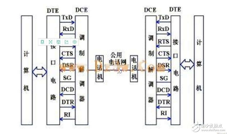
figure 1
DSR, DTR: The Digital Transmitter (DCE) is ready, the Data Terminal (DTE) is ready, and only the device itself is available.
First, the caller is dialed by the telephone, and the telephone exchange sends a dialing call signal to the other party. When the DCE receives the signal, the RI (ringing signal) is valid, and the DTE is notified that the call has been made. When the other party "off-hooks", the two parties establish a communication link.
If the computer wants to send data to the other party, it first sends an RTS (Request to Send) signal through the interface circuit (DTE). At this time, if the DCE (Modem) allows transmission, the CTS (Allow Transmission) signal is answered to the DTE. Generally, the RTS/CTS can be directly connected to the high level, that is, as long as the communication link is established, the signal can be transmitted. (RTS/CTS can be used only for switching between transmission mode and reception mode in a half-duplex system.
When the DTE obtains the CTS signal, it sends a serial signal to the DCE through the TXD line, and the DCE (Modem) modulates the digital signals into analog signals (also called carrier signals) and transmits them to the other party.
Before the computer transfers new data to the DTE "data output register", it should check that the Modem status and data output registers are empty. After the DCE of the other party receives the carrier signal, it sends a DCD signal (data carrier detection) to the DTE of the other party to inform the DTE that it is ready to receive. At the same time, the carrier signal is demodulated into a data signal and sent to the DTE from the RXD line, DTE. The received bit stream is shifted by the serial receive shift register. After receiving all the bit streams of one character, the data bits of the character are sent to the data input register, and the CPU can read the characters from the data input register. .
2, using a dedicated telephone line communicationWhen the telephone line is used for communication between the MODEMs of the two communication parties, the signal lines 2 to 8 are used for communication and control. The telephone, ringing signal RI and DTR signals are not required, and the signal lines are connected as shown in FIG.
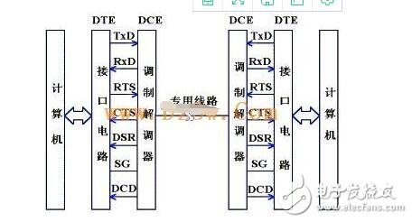
figure 2
Third, short-range communicationWhen the communication distance is relatively short, the Modem is not needed, and the communication parties can directly connect. In this case, only a few signal lines are used. In the simplest case, RS-232C control contact signal is not needed at all in communication. Only three lines (send line, receive line, signal ground) can realize full-duplex asynchronous serial communication, which is discussed here. The first case.
When there is no Modem, the maximum communication distance is calculated as follows:
The RS-232C standard stipulates that when the bit error rate is less than 4%, the capacitance of the wire should be less than 2500 PF. For a normal wire, the capacitance is about 170 PF/M. Allowable distance L=2500PF/(170PF/M)=15M
The calculation of this distance is conservative. In practical applications, when 9600 bps is used, the common twisted pair shielded cable can reach a distance of 30 to 35 meters.
1, the simplest connection of zero Modem (3-wire system)Figure 3 is the simplest connection of the zero MODEM mode (ie, three-wire connection). The cross-connection between the 2nd line and the 3rd line in the figure is because the two sides of the communication are treated as data terminal devices in the direct connection mode, both sides can Hair can also be collected. In this way, either party to the communication can start transmitting and receiving as long as the request to send the RTS is valid and the data terminal is ready for the DTR to be valid.
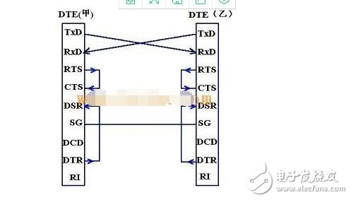
image 3
(1) RTS and CTS interconnection: as soon as the request is sent, it is immediately allowed
(2) DTR and DSR interconnection: As long as the local end is ready, it is considered that the local end can receive it immediately (DSR, digital transmission machine is ready).
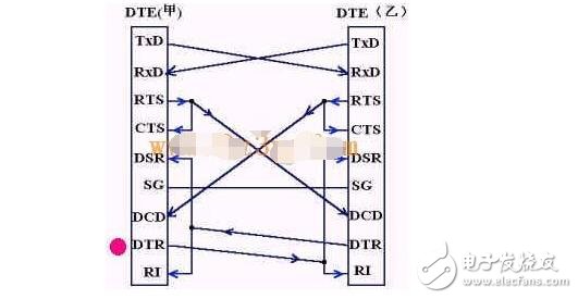
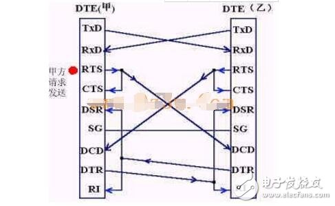
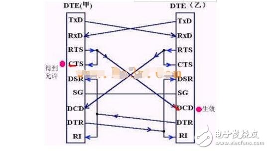
2, zero Modem standard connectionIf you want to connect directly to the RS-232C's contact control signal, use the zero MODEM standard connection method. The signal lines of the communication are arranged as shown in the following order of 1-2-3-4-5. .
The standard connection (7-wire system) without Modem is as shown:
It can be seen that all the signal lines defined by the RS-232C interface standard are used, and are connected according to the requirements of the information exchange protocol between DTE and DCE, but only the signal line sent by the DTE itself is sent. It is the signal sent by the other party's DCE, so this connection is called the two-fork loopback interface.
The handshake signal relationship between the two parties is as follows (Note: Party B's Party B is not marked in the figure):
(1) When Party D's DTE is ready, a DTR signal is sent, which is directly connected to Party B's RI (ringing signal) and DSR (the digital transmitter is ready). That is, as long as Party A is ready, Party B will immediately generate a call (RI) and be ready (DSR) at the same time. Although Party B does not have DCE (digital transmission) at this time.
(2) Party A's RTS is connected to CTS and is interconnected with Party B's DCD. That is, once Party A requests to send (RTS), it immediately obtains the permission (CTS), and at the same time, makes the DCD of Party B valid, that is, the carrier signal is detected.
(3) Party A's TXD is connected to Party B's RXD.
0.8mm ( 0.031") Female Header Connector
Category:Board To Board Connectors
Sub-Category:Pin Header Female
Type:0.8mm
0.8mm ( 0.031") Female Headers Overview
Whenever there is a need for fitting small-sized connectors in compact devices, the 0.8mm pitch female header, or sometimes referred to as header connector, is ideally suited for this application. Not only does this female header space-savvy, but it is also designed for vacuum pick and place that makes it suitable for high volume automated manufacturing.
Antenk offers these low profile, easy-install, SMT or THM miniature female connector plugs at high quality and affordable China-quoted price, for board-to-board connection, snuggly fitting the pins of a male header and acting as a receptacle.
Assembly and service is simple with either vertical (straight), elevated or at a right angle configuration/orientation, which can dissipate current of about 1.0 A or less in a tape and reel packaging. The filleted corners can also remove shadowing allowing optimization of LED output.
Also, the 0.8mm pitch female headers are made to work in Arduino boards, Arduino Pro and Arduino Mega with either single or double-row female headers, facilitating connections for programming and incorporation into other circuits. They have the perfect height for clearing the USB-B connector and great for stacking multiple shields.
Female header always called as [Header connector", Antenk provide widely range of header connector, from 2.54mm (.100″ inch) pitch to 0.8mm (0.031 inch) pitch. The number of pins (contacts) is from 2 to 40 pins per orw. There are three type: Straight (Dip Vertical), Right angle, SMT (surface mount).
If you can not find the items you interest from above items, welcome to contact us, and you will always get fully responsive from us.
Applications of 0.8mm Pitch Female Headers
Its small size is most suitable for PCB connections of small equipment and devices such as:
Arduino Boards
Architectural and sign lighting
Retail and display lighting
Fluorescent LED retrofit lighting
Cabinet or furniture lighting
Commercial / residential cove lighting
WiFi equipment
Gaming consoles,
Measurement instruments
Medical Diagnostic and Monitoring equipment
Communications: Telecoms and Datacoms
Industrial and Automotive Control and Test
Mount Type: Through-hole vs Surface Mount
At one side of this female header is a series of pins which can either be mounted and soldered directly onto the surface of the PCB (SMT) or placed into drilled holes on the PCB (THM).
Through-Hole (Poke-In)
Best used for high-reliability products that require stronger connections between layers.
Aerospace and military products are most likely to require this type of mounting as these products experience extreme accelerations, collisions, or high temperatures.
Useful in test and prototyping applications that sometimes require manual adjustments and replacements.
0.8mm vertical single row female header, 0.8mm vertical dual row female header, 0.8mm Elevated single row female header, 0.8mm Elevated dual row female Header, 0.8mm right-angle single row female header and 0.8mm right-angle dual row female header are some examples of Antenk products with through-hole mount type.
Surface-Mount
The most common electronic hardware requirements are SMT.
Essential in PCB design and manufacturing, having improved the quality and performance of PCBs overall.
Cost of processing and handling is reduced.
SMT components can be mounted on both side of the board.
Ability to fit a high number of small components on a PCB has allowed for much denser, higher performing, and smaller PCBs.
0.8mm Right-angle Dual Row female header, 0.8mm SMT Single row female header, 0.8mm SMT Dual row female header and 0.8mm Elevated Dual Row female Header are Antenk`s SMT female headers.
Soldering Temperature for 0.8mm Pitch Female Headers
Soldering SMT female connectors can be done at a maximum peak temperature of 260°C for maximum 60 seconds.
Orientation/Pin-Type: Vertical (Straight) and Right-Angle
0.8mm pitch female headers may be further classified into pin orientation as well, such as vertical or straight male header or right-angle female header.
Vertical or Straight Female Header Orientation
One side of the series of pins is connected to PCB board in which the pins can be at a right-angle to the PCB surface (usually called "straight" or [vertical") or.
Right-Angle Female Header Orientation
Parallel to the board's surface (referred to as "right-angle" pins).
Each of these pin-types have different applications that fit with their specific configuration.
PCB Connector Stacking
Profile Above PCB
This type of configuration is the most common way of connecting board-to-board by a connector. First, the stacking height is calculated from one board to another and measured from the printed circuit board face to its highest insulator point above the PCB.
Elevated Sockets/Female Headers
Elevated Sockets aka Stacked sockets/receptacles or Mezzanine are simply stacked female headers providing an exact distance requirement between PCBs that optimizes electrical reliability and performance between PCB boards.
Choosing this type of stacking configuration promotes the following benefits:
Connector Isolation - the contacts are shrouded preventing cable connection mishaps and good guidance for the mating header connectors.
For off-the-shelf wireless PCB module, stacking height is optimized with elevated sockets.
Offers superior strength and rigidity.
Polarisation prevents users from inverted insertion.
Single, Dual or Multiple Number of Rows
For a 1.0mm straight or vertical female header, the standard number of rows that Antenk offers ranges from 1 to 2 rows. However, customization can be available if 3 ,4 or n number of rows is needed by the customer. Also, the number of contacts for the single row is about 2-40 pins while for dual row, the number contacts may vary from 2-80 pins.
Pin Material
The pins of the connector attached to the board have been designed with copper alloy. With customer`s demand the pins can be made gold plated.
Custom 1.0mm Pitch Female Headers
Customizable 1.0 mm pitch female headers are also available, making your manufacturing process way faster as the pins are already inserted in the headers, insulator height is made at the right size and the accurate pin length you require is followed.
Parts are made using semi-automated manufacturing processes that ensure both precision and delicacy in handling the headers before packaging on tape and reel.
Tape and Reel Packaging for SMT Components
Antenk's SMT headers are offered with customizable mating pin lengths, in which each series has multiple number of of circuits, summing up to a thousand individual part number combinations per connector series.
The tape and reel carrier strip ensures that the headers are packaged within accurately sized cavities for its height, width and depth, securing the headers from the environment and maintaining consistent position during transportation.
Antenk also offer a range of custom Tape and reel carrier strip packaging cavities.
Female Header Connector,0.8Mm Female Pin Header,0.8Mm Female Header,0.8Mm Pcb Header, Pitch 0.8mm Board to Board Connectors
ShenZhen Antenk Electronics Co,Ltd , https://www.antenksocket.com