2 Characterization of fingerprint images
A pair of fingerprint digital images is a two-dimensional array whose element values ​​are called gray values ​​or brightness values. Before the fingerprint image has not been quantized into a digital image, it is a set of continuous brightness functions, and the feature information of the fingerprint. Among the luminance values, most of the existing fingerprint imaging devices quantize the fingerprint image into 256 different gray levels, and also have 32 gray levels, for the fingerprint identification technology for determining identity. 256 gray levels are the most widely used. The fingerprint images referred to in this paper refer to 256 gray level fingerprint images unless otherwise specified. Figure 2.1 shows a digital fingerprint image of 256 gray levels.

2.1 Geometric characteristics of digital images
For a digital image, if you want to identify and locate the target object, you often use some simple features of the image area, such as size, position, and direction. If the size and shape of the target object are completely different, you can use the scale and Shape characteristics to identify the target object. The size, position, and direction of the digital image will be described below.
2.1.1 Size and location
For an m&TImes;n binary image B[i,j], the area A (or zero moment) of the target area is given by the formula (2.1), the position of the target area, and the position of the center of the area (x, y) In the meantime, the target area center (x, y) can be expressed by the formula (2.2), and the formula (2.2) can be further simplified to obtain the calculation formula (2.3) of the area center.

Where x and y are the number of rows and columns in the image center of the target area

As can be seen from the above equation, the center of the region is a point obtained by globally computing the image, so it is relatively insensitive to noise in the image.
2.1.2 Direction
Calculating the direction of the target object is more complicated than calculating its position. The direction of some shapes (such as a circle) is not unique. In order to define a unique direction, it is generally assumed that the object is elongated and its long axis direction is defined as the direction of the object. . Generally, the smallest second-order moment axis in the same direction as the minimum inertia axis on the two-dimensional plane is defined as the long axis. The second-order moment axis of the object in the image refers to such a straight line, the sum of the squares of all the points on the object to the line is the smallest, taking the binary image B[i, j] as an example, the target area on the image to the minimum second order The sum of the squares of the moments of the moment axis χ2 can be expressed by the formula (2.4). Where rij is the distance from the target area point [i, j] to the line. In the oblique representation of a straight line, when the straight line is approximately vertical, the value of the slope tends to infinity. In order to avoid the numerical ill-posed problem when the straight line is approximately vertical, the straight line is expressed in the form of polar coordinates, as in the formula (2.5). )

As shown in Figure 2.2
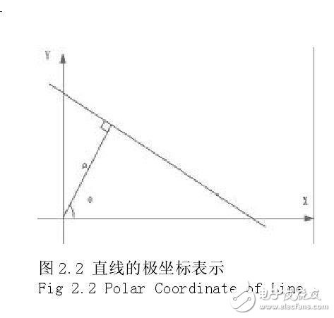
θ is the angle between the normal of the line and the x-axis, Ï is the distance from the line to the origin, and the distance [r, j] in the image is brought into the polar coordinate equation of the line to obtain the distance r, as in the formula (2.6 ) shown

Bringing the formula (2.6) into the formula (2.4) and obtaining the formula (2.7)
![]()
In order to obtain the constant Ï and θ values ​​at the minimum of χ2, we can first obtain the derivative of the formula (2.7), and let the derivative of χ2 to Ï be equal to zero, then we can get the formula (2.8).
![]()
Simplification formula (2.8)

The above equation shows the regression line passing through the center of the object ( x , y). Bring the value of Ï into equation (2.7) and simplify it
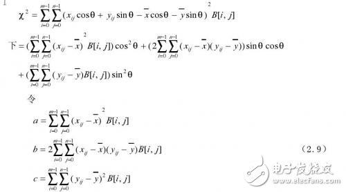
then

For the χ2 differential in the equation (2.10), and the differential result is 0, the equation 2.11 is obtained.

Therefore, the direction of the inertia axis can also be given by the following formula
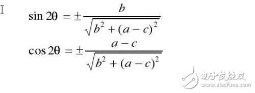
Four values ​​of θ can be determined by Equation 2.12. When θ takes the above value, the value of χ2 may be the minimum value or the maximum value. When χ2 takes the minimum value, the θ value is the normal direction of the inertia axis. The angle with the x-axis, at which point the direction axis can be uniquely determined. If b = 0 and a = c in Equation 2.12, then the direction of the direction axis is not unique, so the direction axis cannot be determined, or the target area has no main direction.
Monocrystalline silicon is an infrared material with excellent comprehensive cost performance. It can be divided into transmission grade and mirror grade. As a transmission grade material, optical grade Czochralski silicon (OCZ SI) is widely used in the mid infrared (1-6um) band, with an infrared transmittance of more than 50%. Zone fused monocrystalline silicon can be used in wider band (1-14um), and high-purity zone fused monocrystalline silicon (hpfz SI) can even be used in far-infrared band (greater than 30um).
Silicon single crystal is also an excellent laser mirror material. Compared with other mirror materials such as copper and molybdenum, silicon single crystal is the preferred substrate material for CO2 laser mirror because of its good thermal conductivity, excellent thermal stability, low coefficient of thermal expansion, relatively low density, low cost and easy precision processing.

Silicon Window
Hanzhong Hengpu Photoelectric Technology Co.,Ltd , https://www.hplenses.com