1 Introduction
With the widespread use of automotive electronics in the entire vehicle, the reliability of automotive electronics has also received much attention. The vibration problem is an important factor affecting the reliability of automotive electronic products. If the vibration characteristics of automotive electronic products can be accurately estimated in the R&D design stage, it is of great significance to the reliability design of automotive electronic products. Using finite element technology to estimate the vibration characteristics of automotive electronics during the R&D design phase, but for electronic products with complex structures, due to model complexity, material parameter uncertainty, boundary setting nonlinearity, computer The impact of factors such as configuration requirements makes the simulation results less credible. Therefore, improving the credibility of simulation analysis is the primary task of today's simulation workers. In this paper, the modal simulation analysis and modal test of a vehicle electronic controller with complex structure are carried out, and the geometric model correction, unit type selection and boundary condition setting in the simulation analysis are studied.
2 Automotive electronic controller structure introduction
The automotive electronic controller consists of a PCBA (integrated circuit board) and upper and lower housings, as shown in Figure 1 (to show the internal structure of the controller, cut off part of the housing). When assembling the controller, first insert the PCBA into the lower casing along the card slot on the casing, and then fasten the upper casing to the lower casing to complete the assembly. The controller is mounted on the vehicle by bolts through the mounting ears on the housing and then to the bracket.
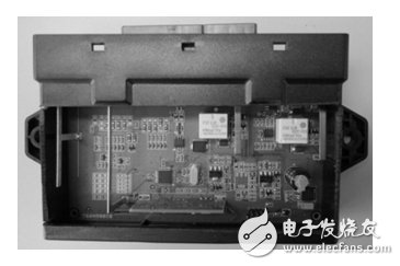
Figure 1: Physical map of the controller
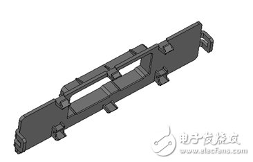
Figure 2: Modified model of the upper casing
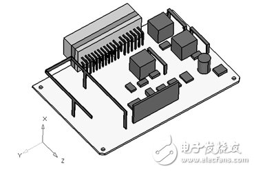
Figure 3: Revised model of PCBA
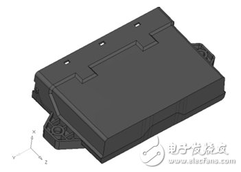
Figure 4: Modified model of the lower casing
3 finite element modeling and simulation calculation
3.1 Geometric model correction
In actual work, it is found that the quality of the geometric model correction determines the quality of the grid. For complex models, without modifying the geometric model, the number of singular elements and the total number of cells are increased, resulting in a longer simulation analysis period, an increase in analysis cost, and even a simulation analysis. The controller's PCBA has hundreds of tiny holes and devices, and the housing has dense hard dots and lines and tiny rounds. If the geometry is not corrected, it is on a medium-sized HP workstation. Unable to complete the analysis. Therefore, before the mesh is meshed, the geometric model of the controller is corrected. Geometric model correction work includes: removing smaller round and round holes; hiding too dense curves and hard points; cutting irregular geometry; ignoring tiny electrical components. The modified geometric model of the controller is shown in Figure 2, Figure 3, and Figure 4.
Fast Recovery Diode (FRD) is a semiconductor diode with good switching characteristics and short reverse recovery time. It is mainly used in switching power supplies, PWM pulse width modulators, inverters and other electronic circuits as high-frequency rectifier diodes. Free-wheeling or damper diodes are used. The internal structure of the fast recovery diode is different from that of an ordinary PN junction diode. It belongs to a PIN junction diode, that is, a base region I is added between the P-type silicon material and the N-type silicon material to form a PIN silicon wafer. Since the base area is thin and the reverse recovery charge is small, the fast recovery diode has a short reverse recovery time, a low forward voltage drop, and a high reverse breakdown voltage (withstanding voltage).
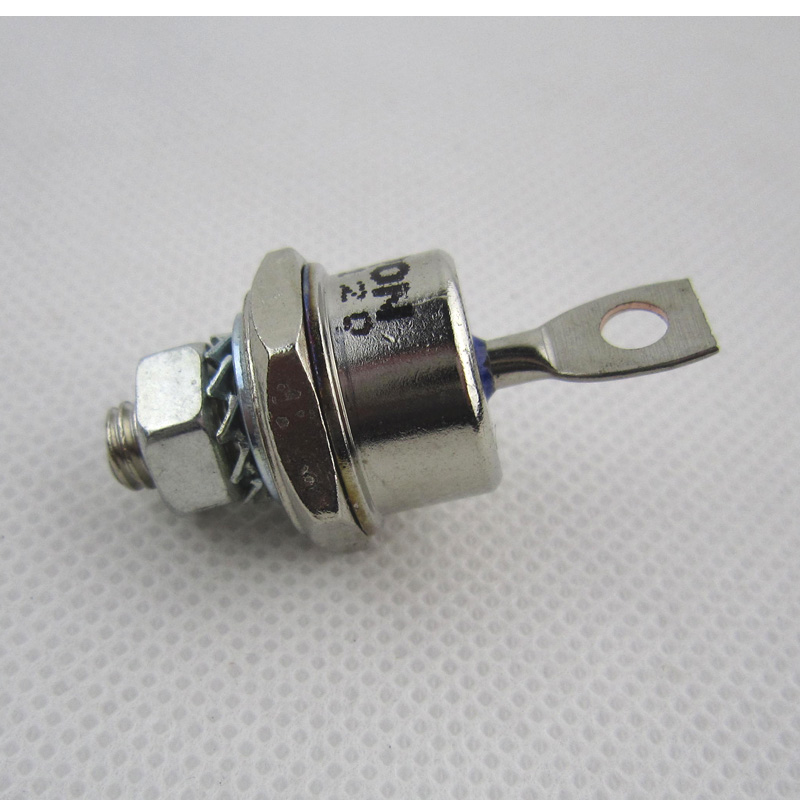
Fast Recovery Stud Diode,Stud Type Fast Recovery Diode,Fast Recovery Diode,Stud Rectifier Power Diode
YANGZHOU POSITIONING TECH CO., LTD. , https://www.cndingweitech.com