Mitsubishi GX-Developer programming software is a Chinese programming software for Mitsubishi series plc, available in Windows 9x and
The above operating system is running.
1 Key features of GX-Developer programming software
GX-Developer is very powerful, integrating project management, program typing, compiling links, simulations, and programs
The main functions of debugging and other functions are as follows:
(1) In GX-Developer, PLC programs can be created by line symbols, list languages ​​and SFC symbols.
Comment data and set register data.
(2) Create a program PLC program and store it as a file and print it with a printer.
(3) This program can communicate with the PLC in the serial system, file transfer, operation monitoring and various test functions.
(4) This program can be debugged from the PLC for simulation.
2 system configuration
(1) Computer
Required models: IBM PC/AT (compatible); CPU: 486 or above; Memory: 8 megabytes or higher (16 megabytes or more recommended); Display: Resolution
The rate is 800 × 600 dots, 16 colors or higher.
(2) Interface unit
FX-232AWC type RS-232/RS-422 converter (portable) or FX-232AW type RS-232C/RS-422 conversion
(built-in), as well as other specified converters.
(3) Communication cable
Use FX-422CAB type RS-422 cable (for FX2, FX2C type PLC, 0.3m) or FX-422CAB-150 type RS-422
Cable (for FX2, FX2C PLC, 1.5m), and other specified cables.
3 GX-Developer programming software installation
Run "SETUP" in the installation disk and follow the step-by-step instructions to complete the GX-Developer installation. After the installation,
An icon corresponding to "GX Developer" will be created on the desktop and created in the "Start\Program" on the desktop.
A "MELSOFT application → GX Developer" option. If you need to increase the simulation function, at the end of the above installation
After that, run “STEUP†under the LLT folder in the installation disk, and follow the step-by-step prompt to complete the simulation function.
installation.
4 GX-Developer programming software interface
GX Developer can be launched by double-clicking the "GX Developer" icon on the desktop. The interface is shown in Figure 1. GX
Developer's interface consists of the project title bar, drop-down menu, shortcut toolbar, edit window, management window and other parts.
In debug mode, you can open the remote run window, data monitor window, and so on.
(1) drop down menu
GX Developer has a total of 10 drop-down menus, each with several menu items. Many basically the same menu items
The usage method is basically the same as that of the menu item of the same name of the current text editing software. Most users are generally rarely directly
Use menu items instead of shortcuts. Commonly used menu items have corresponding shortcut buttons, GX Developer is fast
The key is displayed directly to the right of the corresponding menu item.
(2) Shortcut toolbar
GX Developer has 8 shortcut toolbars, namely standard, data switching, ladder mark, program, comment, soft element
Memory, SFC, SFC symbol toolbar. You can open these jobs by selecting the [Toolbar] command under the [Display] menu with the mouse.
With a bar. Commonly used are standard, ladder mark, program toolbar, mouse over the shortcut button for a while, you can get
The button's prompt information.
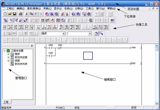
Figure 1 Interface of the programming software
(3) Edit window
The PLC program is input and edited in the editing window, and its usage is similar to that of many editing software.
(4) Management window
The management window implements functions such as project management and modification.
5 Project creation and debugging examples
(1) System startup and exit
To launch GX-Developer, double-click the icon on the desktop with your mouse:
Figure 2 shows the open GX-Developer window.
Exit the GX-Developer system by selecting the [Close] command under the [Project] menu with the mouse.
(2) Management of documents
1) Create a new project: Select the [Project] - [Create New Project] menu item, or press [Ctrl] + [N] to operate in the creation
Select the PLC type in the new project dialog box. If you select the FX2 series PLC, click [OK], as shown in Figure 2.
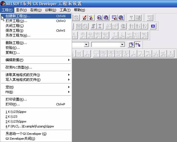
Figure 2-1 Creating a project
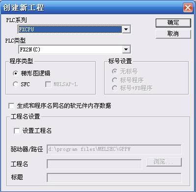
Figure 2-2 Creating a project
2) Open the project:
Open an existing project, select the [Project]-[Open Project] menu or press [Ctrl]+[O], select the existing project in the Open Project dialog box that appears, and click [Open], as shown in Figure 3. Show.
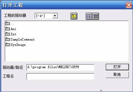
Figure 3 Open the project
3) File saving and closing
Save the current PLC program, comment data and other data under the same file name.
The operation method is: execute the [Project]-[Save Project] menu operation or the [Ctrl]+[S] key operation.
Shut down the PLC program that is already open,
The operation method is to execute the [Project]-[Close Project] menu operation.
(3) Programming operation
1) Enter the ladder diagram
The programmed program is input to the computer using the Ladder Marker toolbar (see Figure 4) or by executing the [Edit] menu - [Ladder Mark] (see Figure 5).
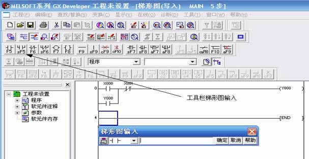
Figure 4 Input ladder diagram
2) Editing operation
The input program is modified and checked by executing the instructions in the [Edit] menu bar, as shown in Figure 5.
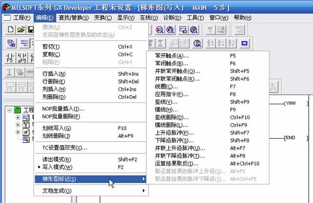
Figure 5 Input ladder diagram
3) Ladder conversion and save operation
The edited program can be saved by executing the [Transform] menu - [Transform] operation or by pressing the F4 key. As shown in Figure 6. The ladder transformation information is displayed during the transformation. If the ladder window is closed without completing the transformation, the newly created ladder diagram will not be saved.
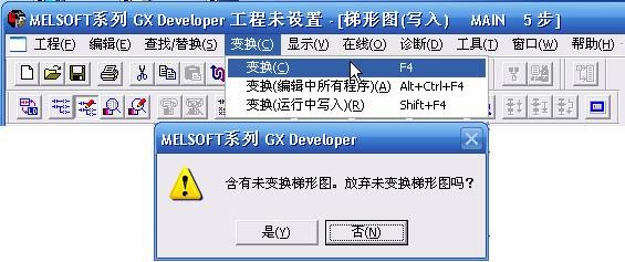
Figure 6 Transformation of the ladder diagram
(4) Program debugging and operation
1) Inspection of the program
Execute the [Diagnostics] menu - [Diagnostics] command to check the program. If the PLC is not connected, Figure 7 pops up:
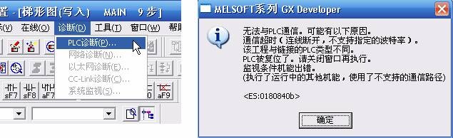
Figure 7 program check
2) Program write
When the PLC is in STOP mode, execute the [Online] menu → [PLC Write] command to send the program in the computer to the PLC, as shown in Figure 8.
Shown. The PLC Write dialog box appears, as shown in Figure 10, select [Parameter + Program], and then press [Execute] to finish writing the program to the PLC.
Figure 8 PLC write
3) Reading of the program
When the PLC is in STOP mode, execute the [Online] menu → [PLC Read] command to send the program in the PLC to the computer, as shown in Figure 9.
Shown
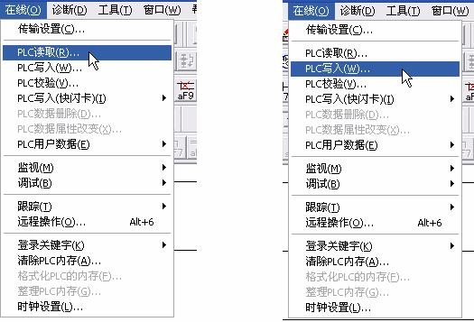
Figure 9 PLC read and write
Pay attention to the following issues when transferring programs.
1 The RS232C port of the computer and the PLC must be connected by a specified cable and converter.
2 The PLC must be in STOP mode to perform program transfer.
3 After executing [PLC Write], the program in the PLC will be lost, and the original program will be replaced by the program being read.
4 When [PLC Read], the program must be read with the RAM or EE-PROM memory protection turned off.
4) Operation and monitoring of the program
1 Run:
Execute the [Online] menu → [Remote Operation] command, set the PLC to RUN mode, and the program runs, as shown in Figure 10;
Figure 10 PLC program operation control
2 Monitoring:
After executing the program, execute the [Online] menu → [Monitor] command to monitor the running process of the PLC. Combined with the control program, the operation has
Turn off the input signal and observe the output status, as shown in Figure 11.
Figure 11 PLC monitoring
Note: Remote operation is also possible in the PLC Write dialog box.
5) Debugging of the program
There are two types of errors that occur during program execution:
1 General error: The result of the operation is inconsistent with the design requirements. You need to modify the program to execute the [Online] menu → [Remote Operation] command first, set the PLC to STOP mode, and then execute the [Edit] menu → [Write Mode] command. Execute from point 3) above (enter the correct program) until the program is correct
2 Fatal error: The PLC stops running, the ERROR indicator on the PLC is on. You need to modify the program to execute the [Online] menu → [Clear PLC Memory] command first, as shown in Figure 12; after clearing all the error programs in the PLC, Start at point 3) above (enter the correct program) until the program is correct
Agriculture Solar Pumps,Deep Well Water Pump,Dc Solar Air Conditioner,Dc Solar Deep Well Water Pump
Wuxi Doton Power , https://www.dotonpower.com