With the development of the economy, the number of cars is increasing, and the pressure on urban roads is increasing. As an effective means to control traffic flow and improve road traffic capacity, traffic lights have obvious effects on reducing traffic accidents. The traditional traffic lights adopt fixed time control, and can not control the traffic light time according to the traffic volume. The traffic time and the traffic flow are often unsuitable, which not only wastes time, but also easily causes “blocking trafficâ€. In order to overcome the phenomenon that the car-free traffic at the green road of the vehicle-less intersection or the green traffic time of the multi-vehicle intersection is short and the traffic is jammed, this paper uses the ultrasonic counting method to design a smart traffic light control for real-time monitoring of traffic flow. Adjustments add flexibility and practicality.
1, system structureThe system is mainly composed of microcontroller module, power management module, ultrasonic vehicle flow detection module, infrared remote control module, crossroad traffic light group and Ethernet interface. The overall block diagram of the system is shown in Figure 1. The system installs an ultrasonic detecting device at each traffic intersection, and the single-chip microcomputer detects the state of the intersection in real time through the device, and controls the traffic light group according to the program logic to realize intelligent control of the traffic light. Due to the limited control capability of the single-chip microcomputer, the traffic police is required to perform manual control under special circumstances. Although the traffic light control system currently used provides human intervention function, it is very inconvenient for the traffic police to control at the traffic light box far away from the intersection. For this purpose, an infrared remote control module is designed, and the traffic police can be anywhere in the intersection. Realize the control of traffic lights.
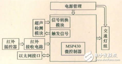
Figure 1 system overall block diagram
An Ethernet interface module is reserved in the system. The collected data can be transmitted to the computer host of the transportation department through the node, providing remote monitoring of the status of the traffic intersection, and also allowing remote control of the traffic light, laying the foundation for the network and information management of the transportation system.
The MCU of the system is selected as MSP430F449, which mainly completes the signal detection, data processing and control of four light groups of the 16 monitoring devices of the system.
2. Vehicle inspection 2.1, installation of ultrasonic testing moduleConsidering that the right turn lane vehicle can pass directly, the ultrasonic sensor is only erected on the straight lane and the left turn lane. Two sets of ultrasonic sensors are installed on the channels in each direction, and the specific mounting positions are as shown in FIG. 2 . The former group is close to the parking line, and the number of vehicles leaving the direction channel is detected (hereinafter referred to as the ultrasonic module group 1); the latter group is set at 80 to 100 m from the parking line (hereinafter referred to as the ultrasonic module group) 2) Detect the number of vehicles entering the direction channel. The difference between the two is the number of vehicles on the channel at that time, and the number of vehicles waiting to pass through the channel. This data is the basis for controlling the transit time of traffic lights at the intersection.
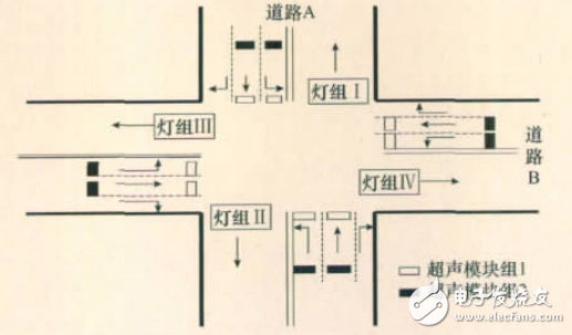
Figure 2 Schematic diagram of the ultrasonic counting module erecting on the plane
2.2, ultrasonic counting moduleUltrasonic ranging is achieved by the ultrasonic pulse echo transit time method. It is assumed that the ultrasonic pulse is emitted by the sensor, reflected by the obstacle, and the total time elapsed until the reception of the echo is t, and the propagation speed of the ultrasonic wave in the air is v, then the distance D from the sensor to the target object can be used.
Formula:
D=t&TImes;v/2 (1)
The principle block diagram of the ultrasonic ranging system is shown in Figure 3.
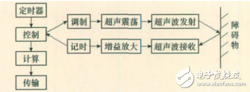
Figure 3 Block diagram of the ultrasonic ranging system
2.2.2, the principle of ultrasonic counting
Ultrasound counting is a deepening application of ultrasonic ranging technology. The ultrasonic ranging module is installed above the lane. The distance measured when there is no car is the distance D1 from the module to the ground. The distance measured when there is a car is the distance D2 from the module to the roof, and the difference between the two measurements. Is ΔD. When the vehicle enters the measurement range of the ultrasonic module, the ultrasonic module first measures the distance D1, and the next period measures the distance D2. The distance difference between the two measurements is ΔD=D2-D1<0; when no car passes, the vehicle There is no change in the distance of the passing process ΔD=0; when the vehicle leaves the measuring range of the ultrasonic module, the ultrasonic module first measures the distance D2, and the next period measures the distance D2, and the difference between the two measured distances is ΔD= D1-D2>0. Therefore, each time ΔD<0 is detected, it means that a car passes under the ultrasonic module, thereby counting the vehicle. The principle of ultrasonic counting is shown in Figure 4.
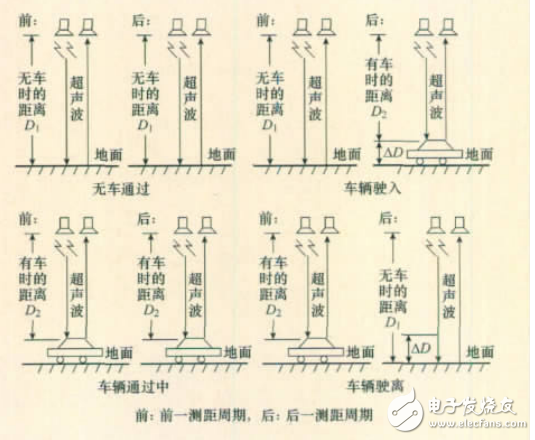
Figure 4 Principle of ultrasonic counting
2.2.3, ultrasonic counting module selection
The system selects the HC-SR04 ultrasonic ranging module to realize ultrasonic ranging. The timing diagram of the module is shown in Figure 5. The pulse width of the module's reverberation level (time of high level) is the distance measurement time, the pulse width is measured, and the distance of the obstacle can be measured by using equation (1). There is a linear relationship between the pulse width and the distance, and by detecting the change in the pulse width, the counting of the vehicle can be realized.
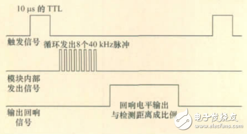
Figure 5 HC-SR04 ultrasonic ranging module timing diagram
2.3. Signal interaction between the detection module and the MSP430From the timing diagram of the 5HC-SR04 ultrasonic ranging module, there is signal interaction between HC-SR04 and MSP430: one is the ultrasonic module trigger signal, which is output from the MSP430 to the HC-SR04; the other is the reverberation level, The HC-SR04 is output to the MSP430. The experimentally measured trigger signal is shown in Figure 6, and the reverberation signal is shown in Figure 7 (the obstacle is at 2.1 m).
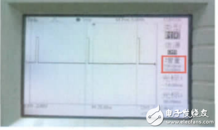
Figure 6 trigger signal
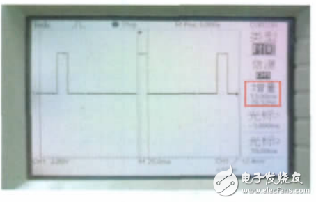
Figure 7 echo signal
From the theoretical analysis, the trigger signal frequency can not be too high, otherwise it will cause signal aliasing, leading to misjudgment; the frequency can not be too low, otherwise the real-time detection of the vehicle can not be realized, so the system selects the trigger frequency to be 10Hz.
Using the capture function of TImerA and TImerB in MSP430, the accurate timing of the reverberation pulse can be realized, and the counting of the vehicle can be realized by the internal program algorithm [7-8]. In order to save the timer resources inside the MSP430, the echo signals of the four intersections of the ultrasound module group 1 are input to the MSP 430 in time division [9]. The circuit diagram of the detection module is shown in Figure 8.
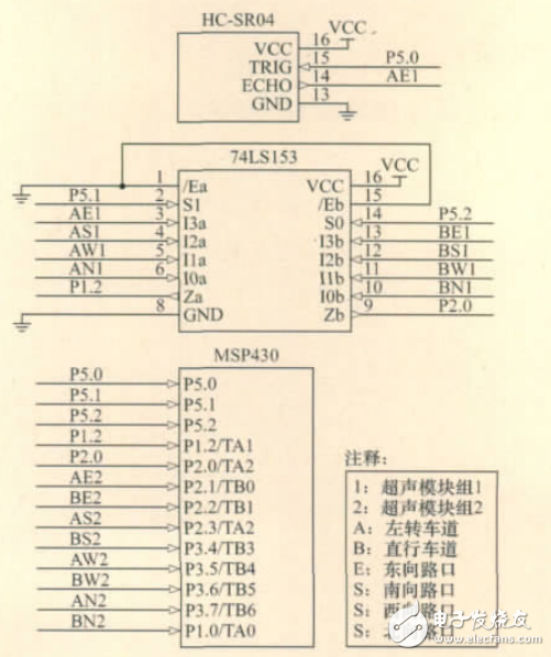
Figure 8 circuit diagram of the detection module
2.4, error analysis2.4.1, ranging error
The system calculates the distance at a sound velocity (340 m/s) at room temperature (15 ° C), while the sound velocity in the actual environment is a random amount, which has the following formula:
v=331.3+0.606c(2)
c is Celsius temperature. According to formula (2):
Sound velocity error
Δv=(c-15)&TImes;0.606
Ranging error
ΔD=TΔv(3)
The ranging error will cause the vehicle to misjudge, which will eventually lead to the allocation of system errors.
In order to eliminate this error, the system does not use a certain pulse width (corresponding to a certain fixed distance) as the vehicle criterion, and the significant variation of the pulse width is the criterion of the vehicle, because the temperature relative ranging time is a slow variable. In the time when a car passes (1s), it is considered unchanged, and this treatment can eliminate the sound velocity error.
2.4.2, the mixed road driving error of the vehicle
Another factor that causes errors is the vehicle's mixed lane travel. One case is that the right-turning vehicle passes under the module 2 to increase the count; in one case, the left- or right-turning vehicle enters the range between the module 2 and the module 1 through the right-turn lane, so that the counting is reduced. However, because of the small probability of occurrence, the two cases have complementary effects, and a small number of inaccurate counts will not have a great impact on the setting of the vehicle's opening time, so it can be ignored.
In summary, the error of the system is within the allowable range, and will not have a great impact on the function of the system. The system can achieve the purpose of intelligently regulating traffic lights.
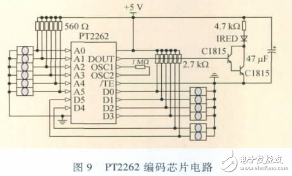
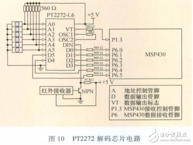
3, infrared remote control module circuit designThe core part of the infrared remote control module is the coded transmission and decoding reception of data. The system uses PT2262 and PT2272 [10-11] infrared emission receiving chips to achieve the above functions. The circuit diagram is shown in Figure 9 and Figure 10.
The traffic light group is a high-power device and cannot be directly driven by a single-chip microcomputer. The system uses the relay to achieve weak current control of strong electricity, and the traffic light drive circuit is shown in Figure 11.
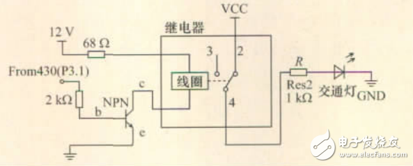
Figure 11 Traffic light drive circuit
5, system software designThe main control program of the system consists of two parts: the traffic flow intelligent processing module and the manual manual processing module. The main program flow chart is shown in Figure 12.
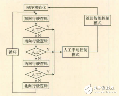
Figure 12 main program flow chart
Vehicle traffic intelligent processing module:
The program performs cycle control on each intersection in time division. The following is an example of the eastward driving lane. The logic diagram of the program is shown in Figure 13.
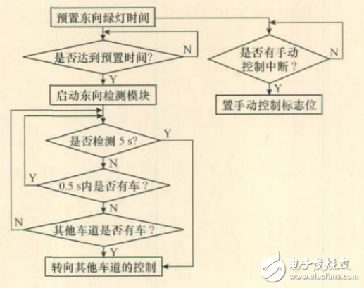
Figure 13 Eastbound driving logic
First, the initial time is preset according to the number of remaining vehicles. The single lane time control table is shown in Table 1. It is assumed here that the number of vehicles in the east lane has been detected to be 25, and the initial time of the system setting is 15s. After the east green light is on for 15s, the eastward ultrasonic module group 1 starts to detect the intersection state. If the detection time does not reach 5s, module group 1 does not detect the passage of the vehicle within 0.5s for a continuous period of time and the vehicle is waiting at other intersections, and the yellow light is 3s in the east direction, turning to the control of the next intersection; if the detection time has been reached 5s, whether there is still a vehicle passing through the east, the east also directly lights up the yellow light for 3s, and turns to the control of the next intersection. In this way, the excess transit time of the car-free lane can be reduced, the waiting time of the vehicles in the remaining lanes can be shortened, and the traffic efficiency can be improved.
Table 1 Single lane time control table

Manual manual processing module: When the vehicle at a certain intersection is greater than the set limit value of 50, it indicates that the intersection has entered a state of severe congestion. At this time, manual control by the traffic police is required. By manually controlling the hardware modules, the opening time of each intersection is manually coordinated to ensure safe driving of roads under congested traffic.
6, the conclusionThe intelligent traffic light control system based on traffic flow detection has certain significance in solving urban traffic problems, improving road utilization rate, improving traffic automation level and management level under certain road facilities and certain traffic flow. The design has low investment, simple production, convenient installation, stable and reliable hardware, and practical functions, and has practical application value.
The Multiple Power Selection Column Loudspeaker Series which produce good clear sound and acoustical clarity for background music and paging,are suitable for indoor and outdoor applications such as stations, gardens, swimming pools,stadiums, and tennis courts, etc.
Even in extreme weather conditions, the all metal extruded aluminum alloy enclosure with cast aluminium top and bottom plates are fully dust and weatherproof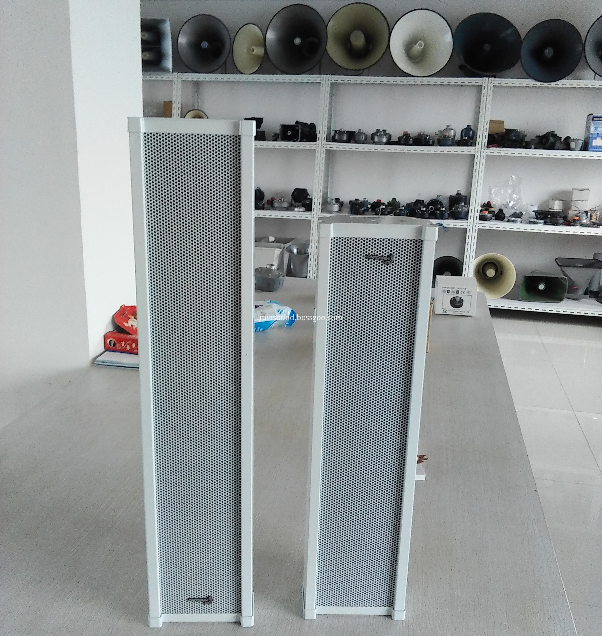
Column Speaker,Column Speakers,Sound Column, Column Loudspeaker, Aluminium Alloy Outdoor Column Speaker
Taixing Minsheng Electronic Co.,Ltd. , https://www.ms-speakers.com