VC++-based analog servo system design Abstract: In the drone semi-physical simulation experiment, in order to save the experimental cost, a method of replacing the real steering gear with an analog steering gear system is proposed. The simulation servo system is designed based on VC++. In the semi-physical simulation system, an analog steering gear is connected, and the system is used to simulate the ailerons, elevators, throttle servos. The effectiveness of the simulated steering gear system was verified through experiments. The experimental results show that the analog servo system has good real-time performance and can simulate the characteristics of various servos.
0 PrefaceUAV flight control simulation mainly includes digital simulation and semi-physical simulation. The semi-physical simulation introduces part of the system into the simulation loop and simulates the actual situation as much as possible. It is more effective than the digital simulation in validating the reliability of the flight control system, especially in its application in the initial stage of flight test adjustment and later stage control strategy improvement.
When making a semi-physical simulation of a drone, a real steering gear is needed, and the steering gear is relatively expensive, and there are risks of damage during multiple experiments, which virtually increases the experimental cost. According to the role and characteristics of the steering gear in the flight control system, an analog steering gear is designed based on VC++. This analog steering gear is composed of a comprehensive record computer and a number of board cards and runs on a comprehensive record computer; instead of realizing the function of a real steering gear, Saves experimental costs.
1 Analog servo hardware designThe analog steering gear system must first simulate the function of the steering gear in the semi-physical simulation; secondly, it must not affect the semi-physical simulation access to the real steering gear. This is selected by PCLD-785B (relay output board). When DO does not output any value, Ci and NCi are turned on. When DO is output, Ci and NOi are turned on (i=0,1,2, …,9).
The system hardware design is shown in Figure 1. For simplicity, the PCL-880 wiring board is omitted.
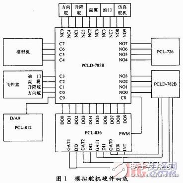
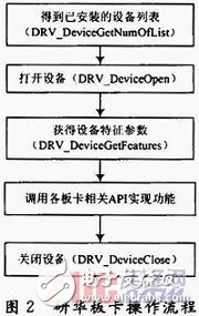
The PCLD-782B in Figure 1 is an opto-isolated board that isolates the PCLD-785B from noise and increases the voltage (the output voltage of the flying control box is 3.3 V, which is increased to the TTL level). The PCL-836 (frequency acquisition card) and PCL-726 (D / A output card), PCL-812 (A / D acquisition card) and located in the comprehensive record computer, in the VC + + operating method shown in Figure 2.
In order to simulate the needs of various servos, the functional relationship of the servos should be adjustable; at the same time, the system must satisfy the servo function of the servos connected to the servos in Figure 1 . The system uses the PCL-836 to send the PWM wave and the PCL-726 collects the feedback voltage. The program interface is shown in Figure 3.
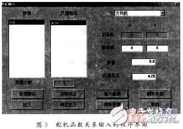
In the figure, k, b is the coefficient in V=kT+b, V represents the feedback voltage, and T represents the pulse width (unit: ms).
3 Analog servo software design3.1 PWM Wave Acquisition Method
The acquisition of PWM is a difficult point of the program. Here, the event count function of PCL-836 is used to measure the PWM. The PCL-836 has a total of 6 counters, of which CLK5 is used to generate the clock signal. The value of the counter is read at the falling edge of the PWM and the PWM high time is calculated based on the clock frequency. A common way to detect the PWM falling edge is to use interrupts and queries. The interrupt is triggered on every falling edge of the PWM and the counter value is read in the interrupt routine. However, the PCL-836 only supports one external interrupt, and it is a rising-edge trigger interrupt. However, the entire simulation requires four servos. It cannot be implemented directly under current hardware conditions, and it requires a certain auxiliary circuit, such as a NOT gate. Secondly, using a query method, one thread reads DI and reads the counter value on the falling edge. However, such a high CPU usage affects the overall performance of the system. So do not use the query and interrupt methods. In order to be able to detect PWM falling edge, and consider the realism, decided to use 1 ms timer to realize. If you read Gao Dingping last time and read low this time, it is considered as a falling edge. Although there is an indefinite delay, the delay is less than 1 ms, and the correct value can be obtained at the same time, and the system occupancy is much lower than the query method.
3.2 Using Multimedia Timers to Acquire PWM Waves
Microsoft provides a low-level API for precise timers, supports timer services that provide high accuracy, and uses multimedia timers to accurately read the current time of the system and handle events at very precise intervals, up to 1 ms. Accuracy. The flow chart of the multimedia timer callback function is shown in FIG. 4 .
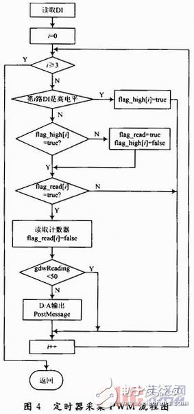
The indefinite delay brought by the method of acquiring the PWM by the multimedia timer and the delay caused by the poor real-time performance of the Windows system make the real-time performance of the analog servo system worse. However, the PWM waves emitted by the flight control box are issued almost simultaneously, that is, the rising edges are consistent in time. So you can use the interrupt plus query method to detect, with a PWM interrupt source, each time to interrupt the query, the final detection of the falling edge.
3.3 Interrupt plus query acquisition PWM wave
PCL-836 supports one external interrupt and rising edge trigger. First use the DRV_EnableEvent function to enable the interrupt, start the interrupt thread, and use the DRV_CheckEvent function to detect the interrupt in the interrupt thread. Interrupt thread flow chart shown in Figure 5.
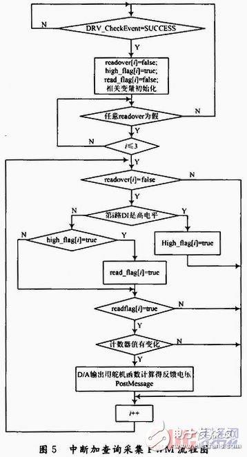
Using the interrupt and query method to acquire PWM, the real-time performance is better, the system occupancy is higher than the timer method, but lower than the query method.
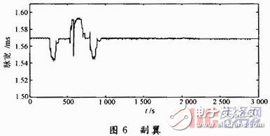
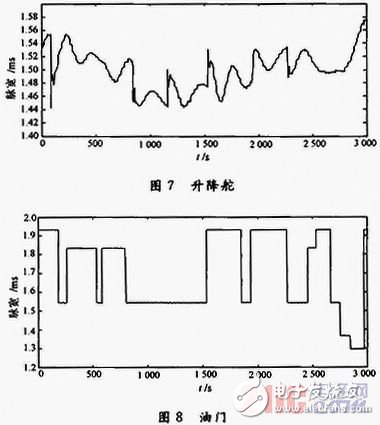
4 Simulation AnalysisIn the semi-physical simulation system, the simulator was connected to simulate the aileron, elevator, and throttle servos. Use this system to collect PWM from the flight control box and feedback the voltage to the model machine. The PWM curves of the servos collected through simulation are shown in Fig. 6 to Fig. 8. It can be seen that the system has good real-time performance and can simulate the characteristics of various servos.
In this paper, based on the analog steering gear system designed by VC++, the function of the real servo in the semi-physical simulation of drone flight control is realized, which reduces the experimental cost to some extent. The system is full-featured, flexible in design, and can realize multiple types of servos. It is an effective simulation method.
The main pain points in obtaining customers in foreign trade are fierce market competition, high customer acquisition costs, low customer stickiness, and single marketing methods. With the changes in the market environment, traditional marketing methods
Orange sample
Guangdong ganzhou , https://www.tlqcjs.com