The traditional drone data recorder is just an on-board electronic device that records the status parameters of the drone during the entire flight process. Most of them use the FPGA as the controller, the NAND Flash as the storage unit, and the SRAM as the data cache, in parallel. Complete data caching and processing [1-2], although it can also achieve effective storage of flight data, but it also has the problem of large power consumption and bulk. Furthermore, FPGAs require external memory modules (such as EEPROM or Flash) to store programming files [2-3], which undoubtedly increases the complexity of peripheral circuits compared to ARM's built-in SRAM and Flash operation and storage programming files. In addition, with NAND Flash as a mass storage device, it is necessary to design corresponding bad block management algorithm and erase balance algorithm, perform real-time ECC verification in the actual storage process, and maintain a NAND Flash bad block table in real time to prevent Writing data into bad blocks can not be read [4-5], which greatly reduces the storage efficiency of the system.
The ever-changing drone applications require data loggers not only to record the flight status of the aircraft, but also to record instructions, data, and work information for various mission equipment for off-line use. Examples of functions are as follows:
(1) Store differential galactic base station and mobile station's original ephemeris data for post-difference decomposition calculation to improve the position resolution accuracy of aerial survey work;
(2) Store all high-frequency raw data of the navigation sensor at rest and during flight, perform off-line noise modeling, and optimize the filtering model;
(3) Record the uplink and downlink data and instructions of the data link on the ground and the aircraft, and analyze the link reliability offline.
In addition to many Other functions that are awaiting development and excavation, these functions require that the data must be stored in such a manner as to be real-time, reliable, low-power, compact, and easy to access. In this paper, a real-time operating system based on embedded real-time RT-Thread data recorder is designed based on practical application requirements in the field of UAV.
1 function module selectionIn order to meet the real-time, reliable, low-power, small-sized, low-cost, and easy-to-access drone data recorder design requirements, the ARM microprocessor must be the most efficient in terms of low power consumption, miniaturization, and low cost. Excellent choice; From the point of view of satisfying real-time performance and high reliability, porting an embedded real-time operating system on a hardware platform ensures undoubtedly the best choice through thread time-sequence rotation; from the perspective of easy access, using an SD card As a storage medium, the system can avoid the waste of CPU resources in links such as erasure and ECC checking. Using USB to read data can improve data reading efficiency.
The hardware embedded platform used by the UAV data logger designed in this paper is the STM32F4 series microprocessor. The SDIO module of the microprocessor is used to read and write the SD card, receive, buffer and store the input data of multiple serial ports, and the USB module. Read the stored data, and transplanted the embedded real-time operating system RT-Thread thread scheduling and file system support, the main structure shown in Figure 1.
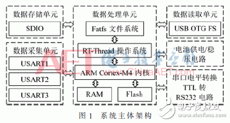
RT-Thread has many advantages compared to embedded real-time operating systems such as EZ C/OS-III and FreeRTOS. The first is open source and conforms to the POSIX specification with high stability. It supports Fatfs file system and adopts a multi-level directory structure. It can perform more scientific file management on drone data of different types, different sources and different purposes, and can implement file transfer with the PC to facilitate data export; adopts a preemptive multithread scheduling algorithm based on priority and Based on the time slice-based rotation scheduling algorithm, the use of kernel objects (including semaphores, mutexes, etc.) for thread synchronization greatly optimizes the execution and scheduling efficiency of threads and improves the data access performance of microprocessors. The effective hardware-driven development and application development can meet the drone industry's requirements for data access.
2 Hardware-driven developmentThe hardware-driven development is mainly in three parts, including the development of serial port modules, SDIO modules, and USB modules on the RT-Thread architecture of the embedded real-time operating system. RT-Thread defines a middle-tier framework for these modules. This framework provides an interface up and down, down to the underlying driver-to-hardware interface. This interface controls hardware modules and obtains data from the hardware. The application interacts with the interface. Through this middle-tier framework, the application program can access the underlying hardware through a unified interface. Even if the hardware has changed, the upper-layer code has almost no need to be modified, improving the portability of the system [6].
The serial port driver mainly includes a serial port initialization program and an interrupt receiving program to achieve fast response to external input data. The SDIO driver mainly includes an SD card initialization program, an SD card product information reading function, and an SD card reading and writing function, which is used to implement the function configuration of the SD card, and also needs to run the Fatfs file system on the SD card to use the file system. Organizational forms for fast storage of serial data. The USB driver is used to implement copying of data stored on the SD card by the PC for processing and analysis on the PC. This requires the development of a USB mass storage device driver [7], and the USB interface is mainly implemented through a descriptor. Description, this article according to the following structure configuration descriptor [8]: a device descriptor, using USB2.0 protocol, and supports a configuration descriptor; a configuration descriptor, contains an interface descriptor; an interface descriptor, interface device class For the Mass Storage class, there are two endpoints; two endpoint descriptors, one IN endpoint and one OUT endpoint are responsible for data receiving and sending, and all use the block transmission format. The maximum transmission packet length is 64B. After the descriptors are configured, the USB can respond to various types of device requests for mass storage and perform data transmission according to the standard USB 2.0 protocol.
Finally, the bottom driver of these three modules is interconnected with the RT-Thread intermediate layer framework, and application development can be performed by calling the standard device interface of the RT-Thread application layer.
3 multi-thread data buffer storage strategyIn applications where the amount of multi-channel data is large and the complexity is high, if the reception and storage of non-periodic byte streams are performed in one thread, it will inevitably lead to frequent writing of the storage device, and the large-capacity storage device mostly uses blocks. Non-bytes are the minimum write units. Writing only a few bytes at a time is the same as writing the entire block. Writing only a few bytes at a time inevitably results in a waste of CPU resources, and storage device reads and writes. Incoming is often the most time-consuming part of a thread, which is bound to reduce the overall system's storage efficiency. If new data arrives during the execution of the thread, the CPU cannot respond in time, which will affect the real-time performance and cause data loss.
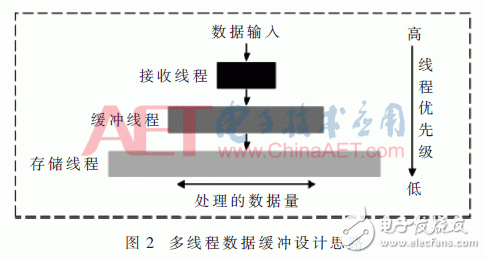
In order to ensure the integrity and reliability of data storage, and no more CPU resources are used to affect the scheduling of other threads, this paper innovatively proposes a multi-threaded data buffering technology that follows the principle of “buffer before storage after receiving firstâ€, that is, designing three threads to receive the data separately. Data, buffered data, and stored data, and reasonable allocation of CPU resources, so that the data received by the receiving thread is minimal, the buffered thread processing data is moderate, and the storage thread processes the most data. According to the conclusions of LIU CL and LAYLAND J proposed in [9] and proved that in the real-time operating system, the thread setting of the RMS algorithm must satisfy the rule that the shorter the period and the higher the priority, so the above 3 The priority settings of the threads should meet the principle of “increasing execution cycle and decreasing priorityâ€. The specific thread design ideas are shown in Figure 2.
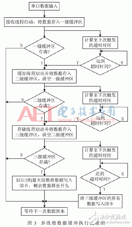
After the actual data arrives, the receiving thread with the highest priority can quickly respond and write the received byte stream to the first-level buffer in time. The size of the first-level buffer can be set to about 256 B. After the buffer is full, it informs the buffer thread to execute. After the buffer thread with medium priority starts, it immediately copies the data of the first-level buffer to the second-level buffer, clears the first-level buffer, and resets the data pointer so that it is not Affects the normal writing of the next receiving task. The size of the secondary buffer can be set to about 2 048 B. It must be significantly larger than the size of the primary buffer. After the secondary buffer is full, the storage thread is notified to execute. After the start of the storage thread of the level, the data in the secondary buffer is quickly copied into the level 3 buffer, the secondary buffer is cleared, and the data pointer is reset so that it does not affect the normal writing of the next secondary buffer. In, the three-level buffer is set to a queue structure. The data copied from the secondary buffer is written into the tertiary buffer in turn according to the queue, since the SD card is a minimum write unit. 512 B. In order to improve the writing efficiency to the storage device, it is necessary to strictly control the number of bytes written to the SD card to be an integral multiple of 512. After the SD card is written, the pointer to the remaining data is moved to the third-level buffer. At the beginning, and put the next shift in the data at the end of these data, to ensure the correctness and efficiency of the next write data, and each thread after the completion of the calculation are synchronized to the next trigger timeout, ensure buffering Even if the data in the area is not full, it can be gradually transferred to the SD card by triggering the timeout. The program execution flow is shown in Figure 3.
After processing the data through the above three threads and three levels of buffers, compared to the use of a single thread for data reception and storage, the problem of data loss and the waste of resources for frequent writing of the SD card are completely avoided, and the serial port is split. The three-threaded CPU time slice rotation process is shown in FIG.
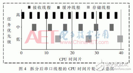
Judging from the time-slice rotation of the operating system's multi-thread scheduling, the receiving thread processes the smallest amount of data, and it occupies few CPU time slices. Even if there is data input during the execution of the buffer thread and the storage thread, receiving Threads can also preempt lower-priority buffer threads and store threads to perform without losing any input data. Moreover, because the receiving thread execution time is short, the execution of the buffer thread and the storage thread can continue from the place where they were preempted, and the data stream is aggregated into data blocks and then written, which significantly improves the data storage efficiency and reduces the SD card reading. Time-consuming writing.
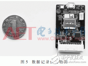
4 System Performance TestIn order to verify the correctness and efficiency of software and hardware design, a small batch of trial production was performed next. The system physical object is shown in Fig. 5, and system performance tests were performed on the data recorder completed.
Develop the following test plan: Connect the PC and data logger, and send the different data to the data logger's 3 serial ports at the baud rate of 115 200 at the same time using the PC software. The frequency is 10 Hz and the data volume is 1 000 B/ Secondly, to imitate the high-frequency sub-continuous data in drone applications, the two methods were tested with single-threaded receiving storage and multi-threaded data buffering. The data was stored on the data logger while the PC was running on the PC software. Simultaneous storage of transmission data, continuous 24-hour continuous stress test, after the completion of the USB port will copy the three different files stored in the data logger to the PC, the transmission data stored in the upper computer as a benchmark, calculate two methods The data storage rate, the actual CPU usage, and the number of SD card reads and writes are shown in Figure 6.
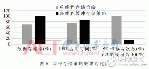
This test scheme not only validates the reliability of the entire system's hardware and software design, but also compares the single-threaded storage strategy with the multi-threaded data cache storage strategy. The test results show that the multi-threaded data buffering strategy increases the actual CPU usage due to the increase of thread scheduling, but this is insignificant compared with the significant increase in the data storage rate, and this method is greatly reduced. The read and write frequency under the same data volume of the storage device prolongs the service life of the storage device, which is obviously better than the single-threaded storage strategy, and can maintain good data storage performance under long-term, big data input stress test conditions. The data storage rate is 100%, achieving the expected results of the design. Finally, the actual application test was conducted. Two data loggers were prepared. One data logger was installed on a small four-rotor UAV. The drone flight data and differential GPS mobile station receiver's post differential data were stored, and the other was stored on the ground. Differential differential GPS receiver data after the actual multi-frequency high-intensity flight using third-party software for post-differential decomposition calculation. After testing, there is no packet loss and the work is normal, which can meet the needs of high-intensity missions.
5 ConclusionIn this paper, a real-time, reliable, low-power, small-sized, and easy-to-access drone data recorder based on RT-Thread is designed for real-world drone industry applications. High-efficiency, high-reliability storage under a large number of continuous data input conditions, and the ability to quickly export stored data to a PC for post-mortem analysis via a USB cable, meeting the increasingly complex requirements of UAV industry applications for data loggers . In addition, the data processing mode of multi-threaded and multi-level buffers is not only limited to the embedded field, but also has some reference for the development of personal computers and server software that require multi-channel data processing.
DMR Digital radios,Motorola Two Way Radios,Motorola Talkabout Radios,Motorola Handheld Radio
Guangzhou Etmy Technology Co., Ltd. , https://www.gzdigitaltalkie.com