Circuit components in practical applications are much more complex than ideal resistors, and exhibit resistive, capacitive and inductive characteristics, which together determine the impedance characteristics. The difference between impedance and resistance mainly lies in two aspects. First, impedance is an alternating current (AC) characteristic; second, impedance is usually defined at a certain frequency. If you measure impedance under different frequency conditions, you will get different impedance values. By measuring the impedance at multiple frequencies, valuable component data can be obtained. This is the basis of the impedance spectrum method (IS), and it is also the basic concept that lays the foundation for many industrial, instrumentation and automotive sensor applications.
The impedance of an electronic component can be composed of resistance, capacitance, or inductance, and a more general case is a combination of the three. The virtual impedance can be used to build this model. The impedance of the inductor is jωL, and the impedance of the capacitor is 1/jωC, where j is an imaginary unit and ω is the angular frequency of the signal. Use complex arithmetic to combine these impedance components. The imaginary part of impedance is called reactance, and the overall expression is Z=R+jX, where X is reactance and Z is impedance. When the frequency of the signal increases, the capacitive reactance Xc decreases, and the inductive reactance XL increases, which causes a change in the total impedance, which is a function of frequency. The impedance of a pure resistor does not change with frequency. .
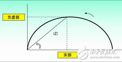
Figure 1: The Nyquist curve when a resistor and a capacitor are connected in parallel.
How to analyze impedanceIn order to detect the impedance of the component, when scanning the device at different frequencies, it is usually necessary to measure the response signal in the time domain or the frequency domain. Generally, analog signal analysis methods are used to measure the frequency domain response signal, such as an AC coupling bridge, but a high-performance analog-to-digital converter (ADC) is used, allowing data to be collected in the time domain and then converted to the frequency domain
Many integral transforms can be used to convert data to the frequency domain, such as Fourier analysis. This method is to take a series of time-domain signal representations of the signal, and then apply an integral transform to map it to the frequency spectrum. Using this method can give a mathematical description of the relationship between any two signals. Of interest in impedance analysis is the relationship between the excitation current (the input of the component) and the voltage response (the output of the component). If the system is linear, the ratio of the respective Fourier transform of the measured time-domain voltage and current is equal to its impedance, and it can be expressed as a complex number. The real part and imaginary part of this complex number constitute the key part of the subsequent data analysis.
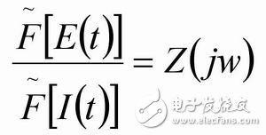
Among them, E=system voltage; I=system current; t=time domain parameter
? = Fourier transform
By converting the complex number form to the polar coordinate form, the relationship between the amplitude and phase of the response signal and the excitation signal at a specific frequency can be obtained.

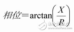
Where R and X represent the real and imaginary parts of the complex number, respectively. The amplitude calculated above represents the complex impedance of the component under specific frequency conditions. In the case of frequency sweep, the complex impedance corresponding to each frequency point can be calculated.
Impedance data analysisThe commonly used method is to use the generated impedance vs. frequency curve as part of the data analysis. When the frequency is swept within a given range, the Nyquist diagram is a curve in the complex plane with the real and imaginary parts of the transfer function as parameters. If the x-axis in the figure represents the real part and the y-axis represents the imaginary part (note: the y-axis takes a negative number), the impedance representation at each frequency point can be obtained. In other words, each point on the curve represents the impedance of a certain frequency point. Can be from the vector length |Z| and the angle between the vector and the x axis? Calculate the impedance. Figure 1 shows a typical Nyquist curve when a resistor and a capacitor are connected in parallel.
Although the Nyquist curve is very commonly used, it cannot give frequency information, so it is impossible to know the frequency value used for any particular impedance. Therefore, the Nyquist curve usually needs to be supplemented by other curves. Another commonly used representation is the Bode diagram. In the Bode plot, the x-axis represents the logarithm of the frequency, and the absolute value of impedance |Z| and phase shift are both represented by the y-axis. Therefore, the Bode plot also shows the relationship between impedance and frequency and phase shift and frequency. Usually the Nyquist curve and Bode plot are used together to analyze the transfer function of the sensor element.
Sensors based on impedance characteristicsConsider a sensor based on impedance characteristics. Under normal conditions, the combination of its capacitance, inductance, and resistance characteristics will produce a specific impedance signal. If a change in the surrounding environment of the sensor causes any change in the above characteristics, it will cause a change in impedance. By measuring the characteristics of this impedance sensor with frequency, a series of new impedance characteristics will be obtained.
A fairly simple method is to compare the measured value of the impedance with the predicted value in order to draw a certain conclusion. An example of this working principle is a metal detection sensor that uses the eddy current principle. A high-frequency AC signal is generated in the coil located in the sensor housing. The electromagnetic field generated by the coil induces eddy currents in the conductive target. In turn, this eddy current interacts with the sensor coil, so it changes its impedance.
.
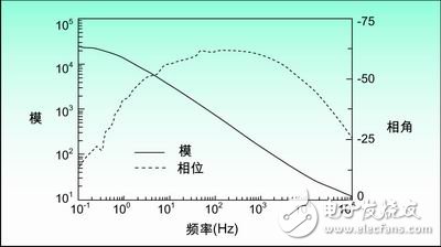
Figure 2: Bode plot showing the relationship between impedance and frequency and phase angle and frequency
Measuring the impedance of a coil as a function of frequency has many advantages. Because the permeability of the material affects the impedance of the coil, some conclusions about the type of metal can be drawn using empirical impedance characteristics. Using this method can also allow the impedance characteristic sensor to detect metals with different permeability. Changes in permeability can also be used to measure metal pressure, because changes in pressure change permeability, and changes in permeability change impedance. Bode plots and Nyquist curves are very useful in checking the frequency response of sensors. Measuring the impedance of a large number of frequency points is more accurate than measuring the impedance of a single frequency point because it helps to remove noise. You can also determine the best operating frequency point by measuring the frequency response of the capacitance component and the inductance component under certain specific conditions.
The method of comparing the measured value of impedance with its ideal value can be applied to many sensor technologies based on the principle that impedance characteristics cause changes in resistance, capacitance, or inductance. Common applications range from gas detection using chemical sensors, humidity sensors based on capacitive characteristics, metal coin or particle feature recognition in the gaming or food industry, to soil monitoring in agriculture.
Impedance analysis involves more than simply comparing impedance response characteristics with their ideal characteristics. Impedance spectrum method (IS) is usually used to characterize the system and obtain valuable information about the system. The purpose of this article is to define the system as a component or a material that is in electrical contact with an electrode. This contact can be the interface between a solid and a solid (in the case of many chemical sensors) or a solid and liquid (when measuring the concentration of a certain component in a liquid). The IS can be used to obtain information about the component itself and the interface between the component and the electrode.
The principle of IS utilizes the fact that if a small potential is applied to the interface, it will be polarized. The combination of the way of interface polarization and the speed of polarization change when the applied potential is reversed can characterize the characteristics of the interface. For the system interface, information such as adsorption and reaction rate constants, diffusion coefficients, and capacitance can be obtained. For the device itself, information about its dielectric constant, electrical conductivity, charge equilibrium mobility, concentration of each component, and mass generation rate and recombination rate can all be estimated.
The equivalent circuit model of the system or component is the basis for analyzing the data generated by the impedance scan. This model is usually a combination of connected resistors, capacitors, and inductors in order to simulate the electrical characteristics of the system. The model we are looking for requires its impedance to match the measured impedance characteristics at different frequencies. In an ideal situation, the selection of model components and interconnection methods should be used to represent specific electrochemical characteristics, and should conform to the physical characteristics of the process. Either an existing model in the literature can be used, or a new model can be established based on experience.
In the case of building a model based on experience, it is necessary to find the best match between the empirical model and the measured data. Because the components in the model do not always conform to the physical characteristics of the electrochemical process, the model can be constructed separately to get the best match. By gradually increasing or decreasing the impedance of the component until the best match is obtained, an empirical model can be established. Modeling is usually done according to the principle of nonlinear least squares fitting (NLLS). With the help of a computer, the NLLS algorithm is used to initially estimate the model parameters, and then gradually change each model parameter, and evaluate the resulting fitting results. The software is used to iteratively process until an acceptable best fitting result is found.
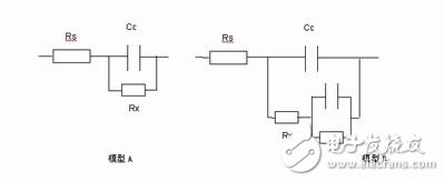
Figure 3. Commonly used equivalent circuit for corrosion analysis
Both data analysis and equivalent circuit models should be treated with great care, and as much model verification as possible. Although it is almost always possible to build a very suitable model by adding components, it cannot be considered that it represents the electrochemical process of the system. Generally speaking, empirical models should use as few components as possible, and physical models based on the theoretical basis of system electrochemical processes should be used as much as possible.
In addition, many different empirical models with the same impedance characteristics can usually be established. Although it is possible to get a good least squares matching model, it is still possible to get an inappropriate model that does not represent the physical system. It is also possible that the NLLS fitting algorithm partially misses the measurement characteristics or does not converge. This is because many algorithms try to optimize the fitting curve in the entire spectrum, so it is possible to miss bad fitting data at certain specific frequency points in the spectrum.
Corrosion analysis is a common application that uses IS method to characterize system characteristics, and it is also a good example. Corrosion of metals (such as aluminum and steel) is a major safety consideration in many industries. If it is not taken seriously, it will lead to the premature end of metal life. The ability to automatically monitor corrosion can significantly save costs, has safety and reliability advantages, and helps optimize preventive maintenance of the system.
In addition to determining the degree of corrosion, it is also possible to predict metal fatigue by monitoring the rate of corrosion. After metal fatigue occurs, the place where small cracks appear will change from elastic to inelastic. These cracks are new, but the corrosion rate is quite fast, and the rate of crack propagation and subsequent corrosion represents the degree of metal fatigue. Early methods of identifying corrosion, especially in locations that are difficult to reach and invisible, can prevent or slow down severe corrosion damage. It can also be used to help identify different protective coatings under realistic conditions.
The following is a corrosion process equivalent circuit model based on physics knowledge and the electrochemical process that occurs during corrosion. The equivalent circuit commonly used for corrosion monitoring is represented by a resistor (Rp) and a capacitor (Cp) connected in parallel and then connected in series with a resistor Rs.
In model A, the resistor Rs represents the solution in which the metal is located, and the capacitance Cc represents the protective coating or paint on the metal surface, which represents the capacitance of the initial coating. After a period of time, water penetrates into the coating to form a new liquid-metal interface. As the metal corrodes, an ion conductive path is formed through the protective coating between the solution and the metal. This can be represented by the parallel model of Rx and Cc. In addition, some models (model B) have an additional circuit in which R and C are connected in parallel and then connected in series with Rx to represent the layered model of the metal protective coating over time.
The resistivity or conductivity of the solution in which the metal is located is usually known or easily obtained, so Rs can be obtained. The value of Cp can also be obtained because it can be calculated from the dielectric constant of the protective coating (usually provided by the manufacturer) and the area covered by it. Then solve for RX to determine the degree of corrosion. Usually the curve fitting algorithm is used to obtain the best fit of the measured impedance characteristic data to solve this problem. Bode plot is also a very common method, which detects the characteristics of the corrosion sensor based on its impedance frequency response and phase frequency response.
The IS method is not only limited to corrosion analysis, but can also be used to characterize a variety of electrochemical systems. For example, it can be used to optimize fuel cell performance, predict battery health, check the concentration of a certain component in a liquid to determine its quality, and characterize the electrochemical performance of a certain material.
Optimize circuit designOnce the equivalent circuit model is determined, an electronic data acquisition system must be designed to complete frequency scanning and obtain data. This is usually a complex and time-consuming task that requires indispensable electronics knowledge in order to optimize the circuit design.
The designed circuit must be able to generate frequency sweeps with the required resolution within a useful range. In many electrochemical systems, it is necessary to avoid the interference of the collected data by the electrochemical process itself. So usually a small AC signal is used, and it is also very important not to introduce a DC potential difference in the system, because it will cause further electrochemical reactions. Then the ADC must be used to acquire the system's response to the excitation frequency. In some designs, two ADCs are required to capture the excitation signal and the response signal respectively. This is very complicated, because two ADCs are required to sample simultaneously in order to detect phase changes between the signals.
AD5933 is a typical integrated circuit chip, which provides a programmable frequency sweep generator and an integrated ADC, which can work with the excitation frequency to obtain the response signal. In addition, the entire system must maintain linearity. In other words, the total bandwidth of the system must be sufficient and the signal size must be sufficient to get good measurement results, but the signal must not be too large to exceed the range of the ADC or other components and cause distortion. Because the impedance range of the component under test is usually unknown, it is usually necessary to do some trial and error at the beginning to optimize the system and ensure its linearity. After converting the response signal into a digital form, the digital signal is usually sent to a computer for further analysis.
The latest solution, such as AD5933, extracts the real and imaginary parts of the response signal before sending it to the computer for processing, and completes a lot of analysis in the chip. This greatly reduces the computational burden of the computer and improves the quality of data acquisition, because the analog signal processing circuit is optimized to work with other functional modules. It should be noted that while keeping the entire system linear, the measurement results of the analog signal must be verified. Otherwise, although the computer can easily provide 4 digits or higher accuracy, the final result will still be biased. Careful system design and verification to obtain effective measurements is the key to improving the accuracy of the final results.
Plug-In Connecting Terminals,Insulated Spade Terminals,Cable Connector Double Spade Terminals,Vinyl-Insulated Locking Spade Terminals
Taixing Longyi Terminals Co.,Ltd. , https://www.longyicopperlugs.com