This year's "Electrical Vehicle Conductive Charging Interoperability Standards" has been released for the final draft, and the electric vehicle and charging pile industry will soon have a detailed test standard. Under the supervision of this test standard, the compatibility of electric vehicles and charging piles will be greatly improved. This article will analyze the interoperability test standards for AC piles.
First, the test system consists of
The standard first mentioned the composition of the AC charging pile test system, as shown. It mainly includes vehicle controller analog box (test charging control process of AC charging pile, abnormal charging status and connection control timing, etc.), AC power (analog grid power supply characteristics), load (simulated battery consumption charging pile output energy), test instrument (Measure the electrical characteristics of the charging pile and the state of the control signal, etc.), the main control unit (control the vehicle controller analog box to simulate the different states of the charging process, and collect and record the test data generated by the test instrument to generate a test report). These parts of the orderly linkage test of the charging pile can greatly improve the testing efficiency.

Figure 1: Structure diagram of AC charging pile AC charging detection system
Second, the charging control process test
The charging control process test of the AC charging post is divided into four phases: connection confirmation test, charge ready test, start and charge phase test, and normal charge end test. The detected contents include the detection point 1, the voltage value of the detection point 4, the frequency of the PWM signal, the rise time, the fall time, the state of charge, and the like.
The test objectives for each phase are
Connection confirmation test: Check whether the power supply device can judge the connection status between the power supply plug and the power supply socket through the voltage value of the detection point 1 or the detection point 4.
Charge Ready Test: Check if the power supply unit can detect that the vehicle is ready and initiate charging.
Start-up and charge phase test: During the charging process, check whether the power supply device can inform its maximum power supply capability through the duty cycle of the PWM signal.
Normal charging end test: Check if the charging device is normal when the vehicle stops receiving charging command.
Third, charging connection control timing test
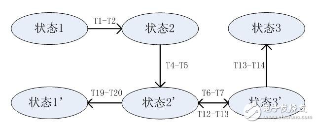
The purpose of this test is to check whether the power supply device charging connection controls various state jumps and time intervals to meet the requirements. The state transition diagram is shown in the figure below. The charging connection timing of the power supply equipment during charging should meet the requirements specified in A.4 and A.5 of GB/T18487.1-2015.

Figure 2 AC charging post charging connection control timing diagram
pet braided cable sleeve,pet braided sleeve,expandable braided pet black cable sleeve,14 inch pet expandable braided sleeving
Dongguan Zhonghe Electronics Co., Ltd. , https://www.zhonghesleeving.com