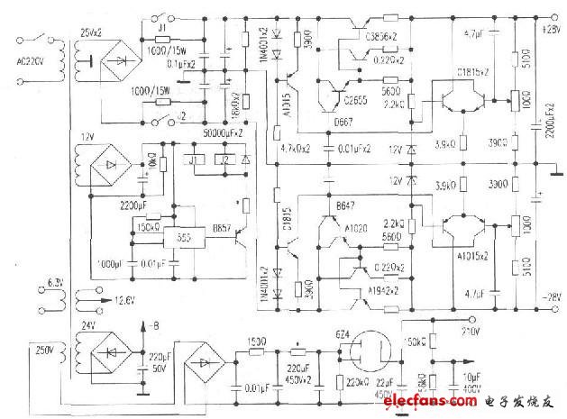
I bought a factory stereo stereo amplifier, connected the CD player and speakers, and turned on the sweet and beautiful sound, which really led the way to the charm of the amplifier. But just after the second song, the sound suddenly became smaller, such as mosquitoes, immediately shut down to check, and found that the surface of the cathode resistance of the two power amplifier tubes 6P1 has burnt into a burnt yellow, which is caused by excessive cathode current. This machine uses a dual triode 6N2 as the pre-amplifier for the left and right channels, and two 6P1 as the Class A amplifier. See the picture for the circuit. The material of this machine is acceptable. 6N2 is the "Beijing" tube. 6P1 is the Hefei tube, and the output transformer and power transformer are of good quality. The resistors are all made of metal film, and the capacity and pressure resistance of the rectifier and capacitor have allowances. The aluminum chassis, wiring and solder joints are also standardized. The overall feeling is a low-cost popular bile amplifier. It is rare that two channels have the same fault at the same time. First check the preamplifier stage 6N2. The measured filament voltage is 6V. Anode voltage 245V. Cathode voltage IV. When a fault occurs, the anode voltage drops to about 220V. After unplugging two 6P1 tubes of power amplifier level, the anode voltage of 6N2 recovers to 245V. After interpolating the output capacitor Cl, no leakage fault was found, but it can be confirmed that the fault occurred at the power amplifier level.
For easy and convenient repair, the right channel power amplifier tube 6P1 was unplugged, and the left channel was interpolated. Immediately after booting, the voltage of V2 (7) pin gate voltage is -0.2V, (3) pin cathode voltage is 12V, and (1) pin screen voltage is 250V, which is normal. But when the fault starts, the grid voltage changes from negative to positive and gradually rises to + 4V, the cathode voltage gradually increases to 35V, and the anode screen voltage drops to about 220V. At this time, the cathode resistor R5 is seriously heated, and it is very likely that the power amplifier tube 6P1 will be burned and shut down immediately.
It can be seen from the circuit diagram. R4 is the gate leakage resistance of V2, which is both the AC load of the previous stage VI and the gate bleeder resistance of the power amplifier stage V2 to discharge the free electrons accumulated on the gate, thereby ensuring the negative voltage of the gate The stability of the power amplifier tube 6P1 is established. R5 is the cathode resistance of V2, and its potential is up, down, and negative. The larger the resistance, the more positive the cathode potential, the greater the electron flow emitted by the cathode and the larger the screen current, so the value of R5 is determined. , Then the cathode current is fixed. The problem is that under the prerequisite of R5 is intact, why the cathode voltage will automatically increase and the grid voltage will change from negative to positive? What is the reason? It seems that this may be the cause of the failure.
The first thought is whether there is a self-excited fault in the circuit. Because the power amplifier circuit is a low-frequency circuit, the possibility of self-excitation is not very large, so try to disconnect the connection from the V2 (2) pin to the output transformer primary, and change to (2 ) A 200fl / 2W metal film resistor is connected in series to the foot curtain grid to (1) the foot screen electrode, to slightly reduce the (2) positive potential of the foot curtain grid to prevent the occurrence of self-excitation, but the test is invalid .
Later, I saw that the two 6P1s were second-hand old pipes, and there was a high possibility of leakage or high temperature short-circuit in the pipe. I borrowed two genuine "Beijing" 6P1s, plugged it in and tried it out, and the failure remained, and so far we are preparing for the exhibition.
Just think about it, there is only one possibility for the grid voltage to change from negative to positive, that is, when the cathode emits electrons that flow too much, the electron flow is attracted by the screen pressure. When running toward the anode, a large number of high-speed electrons hit the residual Of gas molecules, causing them to split into a large number of positively charged positive ions. And these positive ions have no way to gather on the grid of low potential. The more they accumulate, the more the grid voltage changes from negative to positive. When this happens, the condition inside the tube will become more and more Seriously, a vicious circle happened. Because the more positive the grid voltage, the larger the cathode current, but why is the cathode current so large? The only possibility is that the filament voltage of 6P1 is too high, causing the filament current to be too large. Use a multimeter to measure the filament voltage. Up to 12V! Excessive filament current caused excessive emission of cathode current, and this rare failure occurred. After investigation, it was found that the two 6PI filaments should be connected in series to the 12V power supply end. I don't know why the assembler connected them to 12V in parallel. After improvement, troubleshooting.

Fpc Ffc Connectors,Car Charging Connector,Industrial Ethernet Connector,Automotive High Current Connectors
Zooke Connectors Co., Ltd. , https://www.zookeconnector.com