An oscilloscope is a must-have for any design, manufacture or maintenance of electronic equipment. In today's world that changes instantly, engineers need the best tools to solve measurement problems quickly and accurately. In the eyes of engineers, in the face of today's various measurement challenges, the oscilloscope is naturally a key tool to meet the requirements. The use of oscilloscopes is not only limited to the electronic field. The trigger of the oscilloscope can make the signal synchronously sweep horizontally at the correct position and make the signal characteristics clear. The trigger control button can stabilize the repetitive waveform and capture a single waveform. Most users who use oscilloscopes only use edge triggering
Three main trigger modes1. Auto trigger When there is no trigger signal input, or the frequency of the trigger signal is lower than 50Hz, the sweep is self-excited. Whether the trigger conditions are met or not, there is a waveform display, and the trigger position is random. At this time, the waveform "jitter" appears. This mode is suitable for low repetition rates and unknown signal levels;
2. Normal trigger When there is no trigger signal input, the scan is in the ready state and there is no scan line. After the trigger signal arrives, the sweep is triggered. Only display the waveform when the trigger condition is met, and keep the original waveform display when the trigger condition is not met, and wait for the next trigger. This mode is suitable for low repetition rate signals and signals that do not require automatic triggering;
3. Single trigger single button is similar to reset switch. In the single scan mode, the scan circuit is reset when the single button is pressed, and the Ready light is on at this time. A scan is generated after the trigger signal arrives. After the single scan is over, the ready light goes out. A single scan is used to observe aperiodic signals or single transient signals, and it is often necessary to take a picture of the waveform. In the single trigger mode, the oscilloscope is always in a waiting state until a waveform that meets the trigger conditions appears, and then triggers once, and then stops waveform sampling.
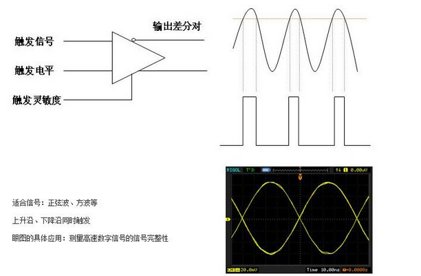
Common trigger methods Edge trigger
Trigger principle: trigger on the trigger threshold of the edge of the input signal.
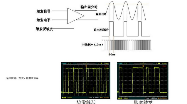
Pulse width trigger trigger principle: determine the trigger time according to the width of the pulse
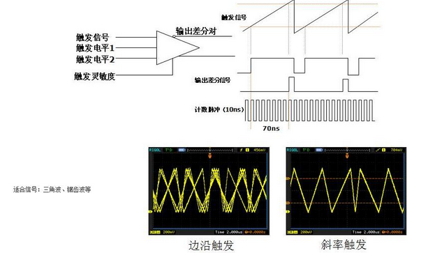
Slope trigger trigger principle: judge according to the rise/fall time of the signal.
Video trigger
Trigger principle: Trigger any line or field on the standard video signal.

Alternate triggering principle: Stable triggering of asynchronous signals.

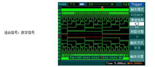
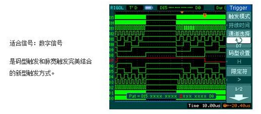
Pattern trigger trigger principle: Pattern trigger refers to a pattern composed of multiple channels. Each channel can determine whether the signal is 0 or 1 according to a preset threshold. Multiple channels 0 or 1 can form a pattern. Oscilloscope That is, the preset code pattern is triggered.
Duration trigger
Trigger principle: trigger within a specified time after satisfying the code condition.
Trigger holdoff
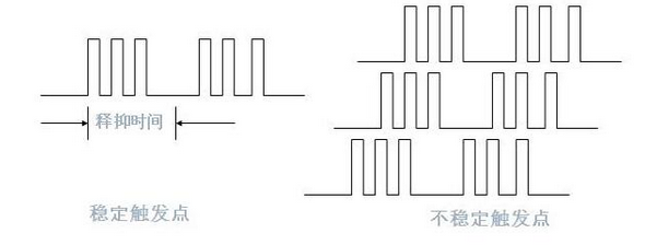
Trigger holdoff means that the oscilloscope stops triggering response within a period of time after the previous trigger. Examples of practical applications: complex pulse trains, amplitude modulated signals.
The core of triggering lies in how to set the conditions. This is the most important part in the use of the oscilloscope, and it is also the most difficult part for many users to grasp. Let’s get to know the commonly used trigger adjustments:
Trigger source
To make the screen display a stable waveform, the measured signal itself or a signal with a certain time relationship with the measured signal must be added to the trigger circuit as the comparison object of the trigger condition, and the comparison object is the trigger source. The most common trigger source is internal trigger (INT), that is, the signal under test is used as the trigger source, such as channel 1, channel 2, and channel 3. When using it, you need to pay attention to selecting the channel where the signal is currently located as the trigger source. This is most of the time. A problem that beginners ignore: Use a channel without a signal as the trigger source.
In addition to internal trigger (INT), there are two trigger sources, external trigger (EXT or AUX IN) and power trigger (LINE). The external trigger is a trigger source independent of the signal channel. The trigger source can only be low-frequency and high-frequency signals, and must have a periodic relationship with the measured signal; the power supply trigger uses the mains input of the oscilloscope as the trigger signal. The method is effective when measuring the signal related to the AC power frequency, and interested friends can understand it by themselves.
Trigger level and trigger polarity
The trigger level is a voltage value in the oscilloscope display. The units are "mV" and "V". In addition, there will be a trigger level line on the interface to indicate its position relative to the signal waveform. The trigger level of the flat-panel oscilloscope is adjusted It's very simple, just touch "Level" with your finger to move online. Trigger level adjustment is also called synchronization adjustment, which makes the scan synchronized with the measured signal. The signal can only be triggered when the trigger level is within the range of the signal amplitude.
The trigger polarity switch is used to select the polarity of the trigger signal. When positive is selected, in the direction of signal increase, a trigger will be generated when the trigger signal exceeds the trigger level. When negative is selected, in the direction of signal reduction, when the trigger signal exceeds the trigger level, a trigger is generated
Hp Laptop 17-By 17-Ca,Hp Laptop Housings,Hp 17 Lcd Back Cover,Hp Back Cover
S-yuan Electronic Technology Limited , https://www.syuanelectronic.com