Research on RCS Visual Calculation Method of Aircraft Cockpit
According to the layered media theory [1] and graphical electromagnetic theory [2], a new method for analyzing and calculating cockpit RCS is obtained and verified. The scattering field on the surface of the low RCS cockpit canopy uses the graphical electromagnetic calculation method (GRECO) Solution, in which the edge effect is estimated by the incremental length ILDC method; the internal structure scattering analysis, the layered medium theory is used to obtain the reflection coefficient and transmission coefficient of the medium cover, and the energy distribution modulation and random phase weighting are used to calculate the internal structure scattering ; Data analysis results are given at the end of this article.
Keywords: layered media theory; graphical electromagnetic calculation (GRECO); CR geometric spline; random phase weighting; energy distribution modulation
The Radar Cross SecTIon of Aircraft Cabin VisualizaTIon CalculaTIve Method
JIANG Xin, NIU Bao-qiang, WANG Bao-fa
(Department of Electronic Engineerng, Beijing University of AeronauTIcs & Astronautics, Beijing 100083, China)
Abstract: Based on the layered-media wave theory and Graphical Electromagnetics Theory, a method of analyzing and calculating the Radar Cross Section (RCS) of aircraft cockpit targets is presented and verified. The cabinsur face scattering fields are obtained by using Graphical Electromagnetic Computation ( GRECO), including cabin wedge scattering fields computed by ILDC method.The reflectance coefficient and the transmittance coefficient are obtained by using the layered-media wave theory.Then amplitude and phase weighing method, called Energy Modulation and Random Phase Weighting method, are used for Calculating the structural scattering fields caused by the objects in the cabin. Numerical results for aircraft cabins are provided at the end of this paper.
Key words: layered-media system; graphical electromagnetic computing (GRECO); CR geometrical spline; phase-weighting method; energy modulation method
1. Introduction It is well known that conventional aircraft cockpits are one of the strong scattering sources directly in front of the aircraft. In order to reduce the contribution of this part to the total RCS, composite hatches with conductive coating and shape stealth measures are often used. This article uses CR spline function Establish a description of the geometric shape of the cockpit, and then obtain a visual electromagnetic scattering model. Use the graphical electromagnetic calculation method (GRECO) to calculate the scattering characteristics of the surface of the cockpit cover with an invisible metal coating. The electromagnetic scattering analysis in the cockpit is very complicated. The reflection coefficient and transmission coefficient adopt the method of amplitude and phase modulation, that is, the method of energy modulation and random phase weighting to calculate the scattering of the structure in the cabin; the total field of the scattering is obtained by the phase superposition of each field, which has practical application value in engineering .
2. Target image generation and visual calculation The shape of the low RCS canopy must have both aerodynamic and electromagnetic scattering characteristics. Advanced fighters mostly use a streamlined waterdrop-shaped structure. Usually there is no analytical mathematical model to describe it Geometric shape configuration. For this purpose, from the point data of the cockpit section type, the Catmull-Rom [3] surface is used for fitting. In this paper, the CR geometric continuous spline function developed in recent years is used to geometrically model the target.
Figures 1 (a) and (b) are the comparison of before and after interpolation using CR spline to a foreign military advanced fighter cockpit grid map. The former has 184 vertices and 354 faces; the latter has 2764 vertices and 5514 faces.

Figure 1 (a) The grid diagram before the cockpit interpolation fitting (b) The grid diagram after the cockpit interpolation fitting By fitting the CR spline surface to the target model, the filtering of the polygonal rough model composed of the type value points to the smooth real model of the complex target is realized. After the geometric description of the target, the standard interface of graphics software (OpenGL ) [4] and the graphics accelerator card hardware to display and blank the target, so as to realize the electromagnetic calculation of GRECO on the computer. The following is the cockpit model displayed by the image generation program. Figure 2 (a), (b) the former is not interpolated The former graph, the latter is the graph after fitting with CR spline. |

Figure 2 (a) Fitting the front cockpit model (b) Fitting the rear cockpit model For the detailed calculation and implementation method, please refer to reference [5]. 3. Scattering analysis of the cabin structure When the radar signal enters the cabin, and then passes out of the cabin after multiple reflections, its propagation direction is unpredictable and its intensity is difficult to estimate. Here, the following methods will be used to solve the problem. First, apply layering Media theory [1] Solve the reflection coefficient and transmission coefficient of the hatch cover.
In the formula
In the formula
Where λ is the incident plane wave wavelength, ω is the angular frequency, ε, μ, and σ are the dielectric constant, permeability, and conductivity of the medium, respectively. For simplicity, the admittance Y of the layered structure is defined as
Therefore, equation (1) can be expressed as
Where [B C] T is defined as the characteristic matrix of the layered structure, and Y = C / B (7) In fact, the reflection coefficient, transmission coefficient and absorption coefficient of layered media can be expressed as
2. Energy distribution modulation method [6]
Therefore, in a certain direction (θ, φ) by σ (θ, φ) = lim [4πR2 Considering that the radar wave enters the cabin through the cabin cover and is scattered back by the objects in the cabin back to the space outside the cabin, it will inevitably produce energy loss through penetrating the cabin cover structure twice, so
Where β is the attenuation factor ∫θdθu∫φd-φ0F (θ, φ) sinθdθdφ = 2φ0 (cosθu-cosθd) (14) due to ∫θdθu∫φd-φ0 make
then σ (θ, φ) = 4πεβF0 (θ, φ) / ∫∫F0 (θ, φ) sinθdθdφ (15) The selection of F0 (θ, φ) in equation (15) should be determined according to the statistical results. For example, for a uniform distribution, F0 (θ, φ) = 1, while for Gaussian and logarithmic distributions, FG0 ( θ, φ) and FL0 (θ, φ):
Where ξ and α are distribution parameters. After determining F0 (θ, φ), equation (15) can be used to solve the RCS value σ (θ, φ) of the interior scattering for a given direction. The outer metal surface part constitutes the total surface effect field Esf, and the edge part constitutes the total edge scattering field Esw. 4. The total scattering field of the cockpit The internal structure scattering and the metal surface part of the cabin constitute the total surface effect field Esf, and the edge part constitutes the total edge scattering field Esw. The RCS value
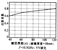
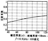
V. Analysis of numerical results For the organic glass with a coating thickness of 40 to 80Å (its thickness is 10mm, the relative dielectric constant and conductivity are εr = 2.62, μr = 1), the conductivity of the film is taken as 5 × 10⁶ (1 / Ω.m), the relationship between the electromagnetic reflectance and the coating thickness at normal incidence is shown in Figures 3 and 4. |

Figure 3 Relationship between reflectivity and coating thickness (re-polarization) |

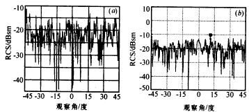
Figure 4 Relationship between reflectivity and coating thickness (horizontal polarization) Figure 5 (a) is the theoretical calculation curve of the aircraft cockpit at 10.5GHz, VV polarization zone with conductive coating (100Å) and cockpit attitude angle (φ, 0,0), and the corresponding experimental curve is shown in Figure 5 (b). |

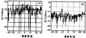
Figure 5 Target: cockpit model, frequency: 10.5GHz, polarization: VV, with conductive coating Figure 6 (a) is the theoretical calculation curve of the aircraft cabin at 10.5GHz, HH polarization, with conductive coating (100Å), and cockpit attitude angle (φ, 0, 0), and the corresponding experimental curve (b) |

Figure 6 Target: cockpit model, frequency: 10.5GHz, polarization: HH, with conductive coating It can be seen from the experimental and calculation results that the average RCS of the cockpit with the coating structure is -15dBSM, the average of the two is consistent, and the overall trend is consistent, which proves the effectiveness of the algorithm. In addition, the cockpit with the coating structure penetrates into the cabin The energy is smaller, and the scattered energy returned to the outside of the cabin is smaller, which is much smaller than the uncoated cockpit. Using the above calculation method can give RCS values ​​for different flight states, polarizations, and operating frequencies. It can be used as an aircraft CAD / CAM A basic module in the system, together with other CAD modules, is optimized to provide a basis for aircraft design. |
PufangTech has designed and produced a number of data radio modems that enable data terminal devices to exchange data from miles away. PufangTech`s radio modems can do the job faster, easier, and less expensively than stringing cable. Easy plug-and-play set-up saves installation and maintenance time.
These compact and rugged units are compatible with Modbus and Profibus so no additional converters are required. They provide a compact and flexible solution for many different long-range applications.
PufangTech`s data radio modems are particularly well suited for outdoor use under varying weather conditions. By using these data radio modems, networks become flexible, easy to expand and can cover a wide variety of solutions from simple point-to-point connections to large networks consisting of hundreds of modems.
Data Radio Modem,Radio Modem,Radio Modem Long Range,Serial Radio Modem
Shenzhen PuFang Technology Co., Ltd. , https://www.hytelus.com

 (6)
(6) 
 (16)
(16)