With the development of industrial automation, remote intelligent meter reading has been developed in the original manual manual meter reading. The existing network intelligently collects the required data from the remote end, then many of them must be unattended. Equipment or monitoring points are not suitable for building a wired communication network. If wireless communication is implemented by means of fiber optics or radio, not only is the equipment expensive, but it is not suitable for mobile. With the generation and full investment of a new generation of mobile communication services, the application of wireless mobile data communication is becoming more and more extensive. Safe data transmission and always-on features, combined with the tariff-based tariff method, make GPRS communication in the industrial control, environmental protection, road traffic, business finance, mobile office, retail services and other industries with unparalleled cost performance advantages . Mobile IP communication using GPRS wireless communication network can be used as a digital transmission channel independently, or as an auxiliary means for erecting optical fibers and digital radio stations.
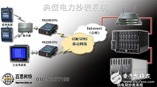
The GPRS remote meter reading integration system is an automatic meter reading system based on GPRS technology. It consists of a power meter, F2103GPRSIPMODEM (GPRSDTU), collector and central server. The collector collects the user's power consumption data in real time, and collects the data to the server through the GPRS network. It has the characteristics of fast and accurate data collection, rapid generation of electricity statistical analysis, payment receipts, etc. Compared with traditional manual meter reading and telephone line meter reading, it greatly improves efficiency. In addition to accurate and real-time meter reading, the system also provides equipment management functions, such as alarms: out-of-box alarms, power-off alarms, reverse-phase alarms, over-temperature alarms, overload alarms, etc.; control: pull-off of arrears users. It also provides power-off data protection function, which can still be used for meter reading and monitoring within 48-72 hours of power failure.
This system combines the SMS platform of Unicom to send text messages to relevant management personnel according to the specific content during the alarm. The system provides a rich interface for linking with the MIS system of the electrical system or for secondary development.
The meter reading software system database is ORACLE database, running on WIN98/2000/XP, NT operating system, easy to use. There is no limit to the number of users the software can manage.
Second, the system architectureThe system consists of a power meter, a collector, a transmission terminal, and a main station with system software. The handheld terminal is a supplement to the system, and manual meter reading is performed in the event of an accident in the system.
2.1 System composition 2.1.1 Energy meter: A) Three-phase active and reactive multi-function meter, active 0.5, reactive 2, with RS485 communication interface, power department DL/T645 communication protocol. B) Three-phase active multi-rate table, active level 1, with RS-485 communication interface, power department DL/T645 communication protocol.
2.1.2 Collector: The main features of the collector are as follows: 24 I/O ports can be used, 24 electric meters can be taken, power failure data protection, with backup power supply, and meter reading can still be performed after power failure.
2.1.3 Transmission terminal: The transmission terminal adopts F2103 of Xiamen Sixin, real-time permanent online, embedded TCP/IP protocol stack with independent intellectual property rights, transparent transmission, supports RS232 and RS485, supports multiple working modes, and supports virtual data. network.
2.1.4 Central Software System: Based on the ORACLE database, the number of users is unlimited, safe and reliable, fast in operation and processing, and rich in functions.
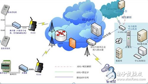
2.2 System General Architecture Multiple meters transmit the meter data to the collection concentrator through the RS485 communication interface. The collection concentrator is connected to the IP modem of the four-letter communication through the RS485 communication interface. The remote data center server can use the APN line or the ordinary ADSL as the network. Access. After connecting to the remote data center server host through the GPRS network and establishing a transparent data channel, the data generated by the collection terminal will be sent to the data center server host as long as it is sent to the serial port; The sent command is sent to the collection terminal through the serial port, thereby realizing the bidirectional transparent transmission of data. The system topology diagram is shown below:
2.3 system function
(1) Set the parameters of the energy meter and read various measurement and management data;
(2) Statistics, query, backup, report, and chart generation of meter reading data;
(3) Plant station management;
(4) Automatic meter reading, timed reporting, real-time query, etc.;
(5) Power-down data storage;
(6) Comprehensive processing of instantaneous amount data;
(7) System data backup, archiving and exporting data to the outside;
(8) Historical data event recording function;
(9) real-time alarm;
(10) Calculate the line loss according to the meter relationship on the line;
(11) It can provide multi-channel analog and digital input, and realize other functions such as unpacking alarm, power failure alarm, reverse phase alarm, over temperature alarm, over voltage alarm, over current alarm, overload alarm, tilt or mobile alarm;
(12) Remote control power-off function;
(13) The collected parameters are rich, such as: a. current, last month, positive active, reverse active, reactive four quadrant total and peak, peak, flat, valley four rate electricity; b. forward, reverse The maximum demand and the maximum demand occurrence time of the active, reactive and reactive power; c active power, reactive power, three-phase voltage, three-phase current, power factor; d cumulative pressure loss, cumulative time of pressure loss, collector Start and stop time of power failure; e unit time load curve, three-phase current curve, three-phase voltage curve, active power curve, reactive power curve, power factor curve.
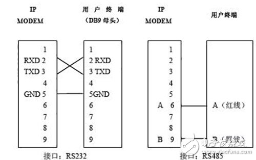
Third, the system architecture implementation3.1 Transmission module and acquisition terminal connection Four letter F2103 wireless transmission module supports RS232/485 interface at the same time, and can communicate with terminal through RS232/485. This system uses the 485 interface mode. The wiring sequence of the F2103 and the collector is as follows:
3.2 Analysis of data center network access methods
1. APN private line access
The center adopts the APN line, all points use the fixed IP of the intranet, and the customer center accesses the GPRS network of the mobile company through a 2MAPN line. The two sides interconnect routers use the private fixed IP address for wide-area connection, and the GGSN and the mobile company interconnect router. GRE tunnels are used.
A dedicated APN is assigned to a customer, and ordinary users are not allowed to apply for the APN. The SIM card used for the GPRS private network can enter the private network APN to prevent the entry of other illegal users.
The user establishes a RADIUS server internally as a remote authentication server for internal users (or enables local router authentication in the APN router). Only authenticated users are allowed to access to ensure internal security.
The user establishes a DHCP server internally (or enables the DHCP function in the APN router) to assign the user's internal address to the authenticated user. End-to-end encryption is used between the mobile terminal and the server platform to avoid possible leakage of information throughout the transmission. Both sides use a firewall to isolate and perform IP address and port filtering on the firewall.
The center adopts APN private line access mode, which has excellent performance in real-time, security and stability, and is suitable for application environments with high security requirements, multiple data points and high real-time requirements. The best way to network when funding allows.
2.ADSL dial-up connection (dynamic public IP address)
The center uses INDSLNET public network connection such as ADSL, and adopts public network dynamic IP+DNS resolution service. The customer first contacts the DNS service provider to open the dynamic domain name. IPMODEM first uses the domain name addressing mode to connect to the DNS server, and then the DNS server finds the central public network dynamic IP to establish a connection. This method can greatly reduce the cost of fixed IP on the public network, but the stability is limited by the stability of the DNS server, so it is necessary to find a reliable DNS service provider. This solution is suitable for small-scale applications.
3. By fixing the public network IP connection
The center uses the INTELNET public network connection such as ADSL, and uses the public network fixed IP service. Such a solution first applies to the Internet service provider for broadband services such as ADSL, and the center has a fixed IP address for the public network. IPMODEM initiates a connection directly to the center. Although the application for fixed IP is relatively expensive, its operation is reliable and stable, and the networking method is simple and convenient. It is favored by users and generally recommended.
3.1 wireless data transmission method
The transmission device has complete functions, stable performance and is easy to use. It is an industrial-grade wireless transmission terminal and has been widely used in various industrial and financial occasions.
After the terminal device and the transmission device are connected, set various communication parameters. After the working mode, fill in the address of the data center and the port number of the application in the transmission device. Thus, when the terminal device data is transmitted to the transmission device, the data is transparently transmitted to the center. The terminal device supports multiple central modes (active and standby center, multi-center), multiple activation modes (telephone, SMS, data), multiple working modes (TCP, UDP, telnet, etc.), which is convenient for user networking and various system requirements. . The heartbeat packet mechanism, the registration packet mechanism, the data frame controllable, the reconnection mechanism and other mechanisms not only ensure that the device is online in real time, but also stable and reliable, and at the same time, it is convenient for the customer to set various transmission parameters according to the situation on the spot, thereby achieving the best effect. .
3.2 Data Center Software Platform Construction
The core part of the meter reading system is the system software, which follows the DL/T645 standard communication protocol and is extensible. The central end software of the GPRS wireless module with four-letter communication has many ways. For different ways of incoming data, we provide different software to help customers quickly realize data reception and field device management at the central end. Central interface:
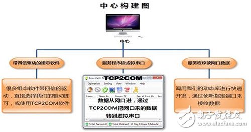
The following is the central station software of the system: the first graphical web interface, the second is the central station developed with VB.
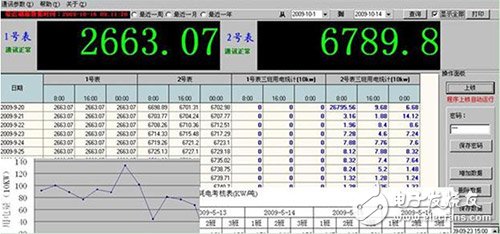
In terms of system security, in addition to the large-scale, multi-user ORACLE database, the system implements hierarchical authorization management and provides firewall functions and perfect data backup functions for users, the company also provides security technology solutions for network wireless data monitoring centers. To ensure data is safe and reliable.
Wireless Bridge,Wireless bridge Access Point,Indoor wireless Bridge,Wireless Bridge Outdoor
Chinasky Electronics Co., Ltd. , https://www.chinacctvproducts.com