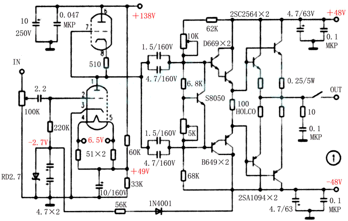
In order to improve the sound quality, reduce interference and stabilize the working point, the following measures were taken for the power supply of PCC88 filament: 1. Buck power supply. The filament voltage is reduced from the standard 7V to 6.5V, which can greatly reduce the thermal noise of the tube and increase the stability of the circuit. 2. The filament power supply is obtained from the switching power supply through the LM317, and adopts a suspended structure to avoid the impact on the working state of the electronic tube and the sound quality, 3. Increase the filament potential, divide the anode voltage through two resistors, and raise the filament potential to 1/3 times of the positive pressure (the two resistors also serve as high-pressure discharge), reducing the filament and anode, especially with U2 The potential difference between the tube grid and the cathode can effectively reduce noise interference. 4. Use fixed grid bias. -48V power is reduced to -2.7V by a 56k resistor and RD2.7 stabilizing tube. It is isolated by a 220k resistor and connected to the grid. The cathode is directly grounded. The frequency response and distortion index of the large electrolytic capacitors connected in parallel are reduced.
The current amplification stage adopts a three-stage emitter follower, which sets a sufficient current gain to reduce the burden on the anterior bile duct. Two pairs of D669 / B649 are used to form the Darlington tube structure, which can eliminate the saturation shaving phenomenon caused by signal overload. When the front-stage tube is close to saturation, the current gain will rapidly decrease, so that the water of the last-stage tube will not enter the saturation zone far, and the signal "soft landing" will be achieved to avoid harsh distortion. Negative feedback is completely eliminated, and push-pull circuits are used at all levels.
The last stage uses two pairs of Toshiba Hi-Fi pair tubes 2SC2564 / 2SAl094 for parallel output. The tube fT = 90MHz, is three times the characteristic frequency of the common 2SC3280 / 2SAl301, current 12A. Power 120W. For the promotion level, the Hitachi fever pair tube 25D669 / 2SB649 is used. The fT of the tube is up to 140MHz and the power dissipation is 20W. Using it with the 2SC2564 / 2SAl094 partner can output a very warm and sweet tone.
The final stage is designed as a high-bias class A and B output, the tube static current is set to 360mA, so that the power amplifier tube always works in the linear amplification area, and at the same time, it can also get a class A power (8Ω) of about 8W. For class B output, the maximum output Power up to 140W!
Use high-frequency switching power supply as the energy supply of the whole power amplifier (see Figure 2). The tube power supply uses the Sanyo 83P movement color TV switching power supply circuit, which is self-made with slight modifications. The rear stage power supply uses two Taiwan-made Mingwei brand industrial-grade S-320—48 switching power supplies to form a ± 48V, 6.5A power supply, with a power of 320W, a switching frequency of 167kHz, and overcurrent, overvoltage, overheating, etc. Protection function, built-in automatic air cooling system.
Follow the star-point one-point grounding rule on the circuit layout. Except that the static working point of the final transistor needs to be patiently and repeatedly debugged, the whole machine can get a beautiful and beautiful playback effect without too much adjustment.

Follow WeChat

Download Audiophile APP

Follow the audiophile class
related suggestion
Avago Introduces New High Linear Power Amplifier Module Product Avago Technologies ...
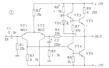
The circuit is shown in Figure 1. The chip IC uses the LM1875 of the American NS company, which has a soft tone and low distortion (0.015% ...

The word "Monster" has both positive meaning and ...
When the output power of the digital power amplifier is greater than 50W, it is impossible to use only ...
If an "audiophile" is a group of people who are never satisfied with the sound and "loved the new and the old" with the audio equipment. Then just rely on these so-called "fever spirits" ...
First, the circuit principle and characteristics 1. Power amplifier part (see Figure 1)
There is a well-known saying in the Hi-Fi world that is "briefness first." This means that if ...
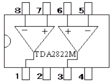
Simple and practical TDA2822M integrated power
TDA2030 is ...

STK465 thick film ...

This RF power amplifier can output 2-3 channel signals, covering an area of ​​about one square kilometer, is ...
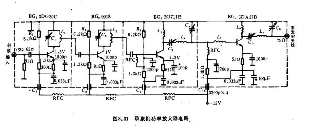
![[Photo] 15w RF power amplifier](http://i.bosscdn.com/blog/20/06/41/521040781.gif)
![[Photo] Broadband high frequency power amplifier](http://i.bosscdn.com/blog/20/06/41/520536801.jpg)
Low frequency power amplifier
![[Photo] TDA2030 audio power amplifier](http://i.bosscdn.com/blog/20/06/41/5131012891.gif)
Looking at the Hi-Fi amplifiers currently on the market, the output power is 100W ...
![[Photo] Transistor 15W Class A Power Amplifier](http://i.bosscdn.com/blog/20/06/41/513102891.gif)
With the newly launched LM4651 and LM465 from National Semiconductor ...
![[Photo] 125W Class D Subwoofer Power Amplifier](http://i.bosscdn.com/blog/20/06/41/513100868.jpg)
![[Photo] Mark Levinson No. 30 ...](http://i.bosscdn.com/blog/20/06/41/513544752.jpg)
EL34 (6CA7) was first launched by Philips in 1956 ...
![[Photo] 45W transistor tube hybrid power amplifier](http://i.bosscdn.com/blog/20/06/41/513531952.jpg)
This article cleverly combines the electronic tube EL34 and the transistor (op amp), ...
![[Photo] 32W hybrid audio power amplifier](http://i.bosscdn.com/blog/20/06/41/513526493.jpg)
"Simple" means the circuit of the amplifier is simple, making it easier, as long as the picture ...
![[Photo] Simple fool power amplifier](http://i.bosscdn.com/blog/20/06/41/513432946.jpg)
1. Description: & nb ...
![[Photo] LM386 low voltage audio power amplifier ...](http://i.bosscdn.com/blog/20/06/41/513417261.gif)
The Class A transistor power amplifier has a warm and sweet tone, which makes people tempted. But the temperature rise of Class A amplifier ...
![[Photo] Class A power amplifier using SAP15N / P audio pair tube ...](http://i.bosscdn.com/blog/20/06/41/513346769.gif)
The circuit is shown in Figure 5, ...
![[Photo] Using TDA7294 and 2SA1216 / 2S ...](http://i.bosscdn.com/blog/20/06/41/4233420295.gif)
