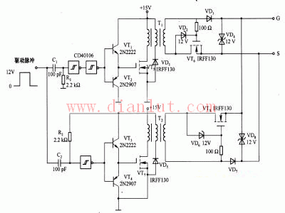
The following is a circuit diagram of the MOSFET gate drive circuit principle
MOSFET gate drive circuit principle
Principle: The following figure is a power MOSFET gate drive circuit composed of a transistor or the like.
The circuit consists of two forward converters: one is the converter that charges the gate capacitance of the power MOSFET; the other is the converter that discharges its gate capacitance.
The recommended supply voltage is 12-15V. At the rising edge of the drive pulse, VT5 receives the pulse. For the values ​​of Cl and Rl given in the figure, the typical duration is 2OOns and the pulse is transmitted to the secondary of transformer T1. When VT6 and VD3 are properly biased, the secondary pulse charges the gate-source capacitance of the driven power MOSFET and then turns off the current path. On the falling edge of the drive pulse, VT7 receives the pulse and transmits the pulse to the secondary of transformer T2.
When VT8 and VD7 are properly biased, a discharge loop is provided for the gate-source capacitance of the driven power MOSFET. When the transformers T1 and T2 have no signal transmission, the gate-source voltage of the driven power MOSFET is completely blocked, and the gate-source capacitance is neither charged nor discharged, so the operation of the driven power MOSFET The point remains the same. The third winding of the transformer is used to bleed the magnetizing current, allowing the circuit to operate at high frequencies if the transformer is not saturated.

Furniture Aluminum Alloy Die Casting
Furniture Aluminum Alloy Die Casting,Aluminium Section Die Casting,Door Frame Die Casting,Handle Bathroom Die Casting
Dongguan Metalwork Technology Co., LTD. , https://www.diecast-pro.com