Usually, the mouse converts the distance and direction of movement into a pulse signal to the PC in a wired manner through the PS2 jack or the USB interface. In recent years, with the development of wireless technology, a new type of wireless mouse has emerged, which is free from the constraints of the mouse line and makes the mouse move. As a DIY enthusiast, the author based on the principle of "do it yourself, full of food and clothing", based on the working principle and protocol of the mouse, using the old PS2 mouse and 315M wireless transmitter and receiver module, with the PC serial port, made a simple wireless Serial mouse, the cost is only about 20 yuan.
hardware design
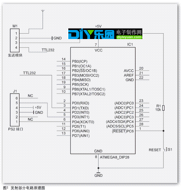
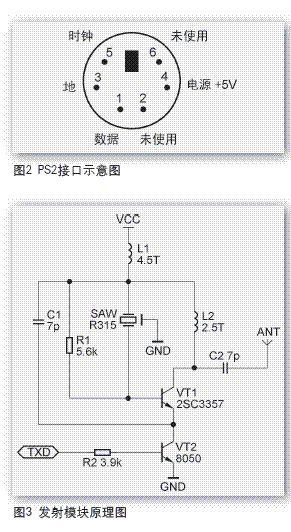
The wireless mouse is divided into two parts: signal transmission and signal reception. The schematic diagram of the transmitting part of the circuit is shown in Figure 1, where the pin definition of the mouse PS2 interface is shown in Figure 2. The transmitting part of the circuit is mainly composed of the AVR single-chip machine ATMEL Mega8 (hereinafter referred to as Mega8) and the 315MHz transmitting module. Here, Mega8 mainly completes the control and data acquisition of the PS2 interface mouse, and transmits the displacement data through the 315MHz transmitting module.
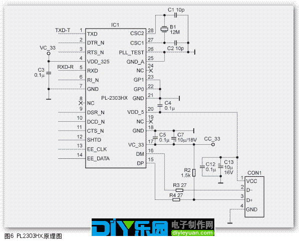
The circuit diagram of the commercially available 315M transmitting module is shown in Figure 3. The receiving part of the circuit is mainly composed of the receiving module and the MAX232, and its schematic diagram is shown in FIG. The LED is used to indicate the reception and demodulation of the wireless signal, and the LED should flash when there is data reception. The circuit schematic of the commercially available receiving module is shown in Figure 5.
※Note: In order to make the module work in the best state, the author made some minor adjustments to the transceiver module, which will be described in detail in the production method.
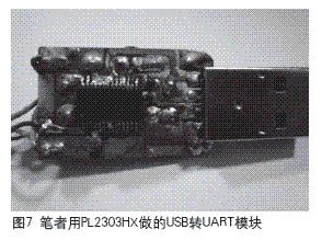
Considering that the notebook computer has gradually eliminated the serial port, the USB to UART chip such as PL2303HX can be used instead of MAX232, as shown in Figure 6, the physical circuit is shown in Figure 7. The main body of the circuit is the PL2303HX chip, the main
To complete the protocol conversion between USB and TTL232. For a detailed introduction, please refer to the article "Common USB to Serial Port Chip Introduction" in the fifth issue of this issue.

software design
After the Mega8 will transfer the read mouse displacement data to the PC through the 315M transmit-receive module, the mouse shift data will be processed. The author used VS2005 C# to write a simple serial port small program. The program interprets the received data and converts it into a trajectory of mouse motion. Used by the author, the effect is good. The specific code will not be described in detail here. Please download it from our website.

Production Method
The method and main points of the wireless mouse:
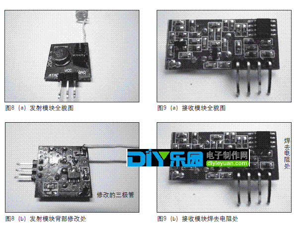
1. Since the serial port of the MCU is not high when transmitting data, the circuit of the transmitting module according to Figure 3 will continue to send wireless signals when the serial port is not sent. Therefore, the author compares the VT2 in the module (generally two in the module). A small patch transistor is changed to a PNP type transistor, such as 8550, 9012, etc., as shown in FIG. After this modification, the transmitting module only generates the 315MHz modulation signal when transmitting low-level data, which conforms to the characteristics of the serial low-level start bit, and saves a considerable part of power consumption.
2. The author finds that the output signal of some receiving modules is always around 1/2V DD, such a signal must not be correctly received by the serial port of the microcontroller. Through analysis, the author removed the resistance (R11) between IN+ and IN- of the LM358 post-amplifier, and the effect is satisfactory, as shown in Figure 9. It is low when no signal is received and high when it is received. Of course, the performance of different receiving modules is endless.
In the same way, if the reader encounters such a phenomenon during production, try the author's method.
3. The antenna of the transmitting module and the receiving module can be selected from (1/4l) hard copper wire of about 23.8 cm, wrapped in a spiral shape on the pencil and appropriately elongated. The antenna has a certain directionality, which is closely related to the strength of the received signal.
4. Since this code does not involve accurate delay, the internal RC oscillator can be selected to use 8MHz when programming the AVR fuse bit. The AVR series MCU and the 51 series MCU have different port structure, and its input and output conversion needs to be realized by modifying the register (DDRx). Therefore, the direction of the port needs to be distinguished when reading and writing. In this circuit, I only use PD3 (CLK connected to PS2) and PD4 (DATA connected to PS2). I use PD3 to detect the falling edge of PS2 to generate an interrupt, and press Bit to read the serial data of PS2. Of course, the reader can also modify it to apply to a smaller AVR microcontroller or even a SMD packaged microcontroller.
5. The PC software of the author is developed by C# and belongs to the application under the .net environment. Considering the simplicity of the mouse production, the author did not adopt the driver development method for data processing, but used the simple and easy-to-understand mouse API control function to control the mouse, which can better meet the needs of mouse control. The software interface is shown in Figure 10.
Some readers may try to install Microsoft's FrameWork 2.0 environment when they encounter a double-click error that cannot be run. The download address is ?FamilyID=0856EACB-4362-4B0D-8EDD- AAB15C5E04F5&displaylang=zh-cn.
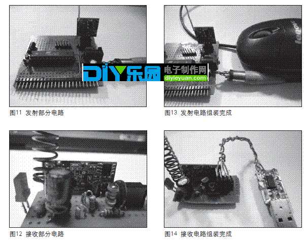
6. If you need to use PL2303HX instead of MAX232 chip, you need to install the driver on the PC. For details, please refer to the article “Common USB to Serial Port Chip Introduction†in the May 2008 issue of this journal. The pictures produced are shown in Figures 11-14.
Review
Interested readers can use a smaller, low-voltage chip to make the structure more reasonable and more beautiful. The author will use the wireless transceiver module as the medium for the serial data packet containing the mouse positioning point to realize the wireless data transmission and acceptance, thus completing the production of the wireless mouse, which has wide application value from the perspective of versatility and ease of use. However, the author's design still has many imperfections.
Gas Stove,Single Burner Gas Stove,Tempered Glass Panel Gas Stove,Stainless Steel Gas Stove
Shandong Sangle Group Co.,Ltd. , https://www.sangle-group.com