The wire resistance on the single bridge arm and the contact resistance at the contacts are on the order of 10-3 ohms. Since these additional resistors are much smaller than the bridge arm resistance, their effects can be ignored. However, if it is used to measure resistances below 1 Ω, the effect of these additional resistors on the measurement results is highlighted. The Kelvin double bridge can be used to measure resistance from 10-6 Ω to 10 Ω, effectively reducing the effects of additional resistance.
1) Principle of double bridge circuit structure and the effect of reducing the additional resistance
Figure 17-1 (a), (b) is a double bridge line structure and its equivalent circuit. The double bridge has two significant differences in the line structure from the single bridge: 1 the resistance to be tested Rx and the bridge arm resistance RN (standard resistance) are four-terminal connection method; 2 adding two high-resistance resistors R3, R4, The "internal arm" that constitutes the double bridge.
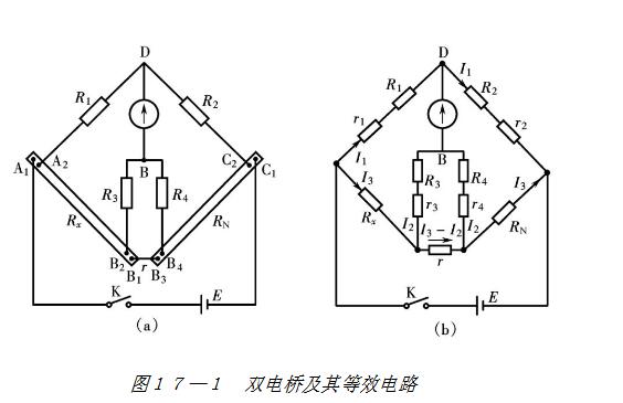
The two contacts on the outside of the four-terminal resistor are called current terminals and are usually connected to the power supply circuit, thereby folding the additional resistance of the current terminal into the resistance of the power supply circuit. In Figure 17-1, the additional resistors of the two contacts A1 and C1 are folded into the internal resistance of the power supply. The two contacts B1 and B3 are connected by short and thick wires, and the additional resistance between B1 and B3 is R. It will be proved later that if R1, R2, R3, R4 and RN satisfy certain conditions, the influence of R on the measurement result can be reduced.
The two contacts on the inside of the four-terminal resistor are called voltage terminals, and are usually connected to a high-resistance loop or a compensation loop with zero current. In Figure 17-1, the contact resistances of the A2 and C2 terminals are respectively incorporated into R1 and R2; the contact resistances of the B2 and B4 terminals are respectively incorporated into R3 and R4. Since R1, R2, R3, and R4 have high resistances themselves, these additional resistors have little effect on them. In addition, the part between the voltage terminals is the low resistance itself, and there is no additional connecting wire, so the influence of the wire resistance is effectively eliminated.
2) Balance conditions of double bridge
To adjust the balance, the resistances R1, R2, R3, R4 and RN are adjusted so that the two potentials of B and D are equal, and the galvanometer current Ig=0. From the direction of the current shown in Figure 17-1(b), consider the equation R1, R1, R2, R2, R3, R3, R4, R4, which can be listed.
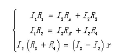
Joint solution
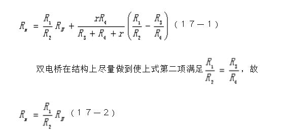
Equation (17-2) is the equilibrium condition of the double bridge. As long as the low resistance to be tested is connected to the measurement by the four-terminal connection method, the Rx can be calculated by the equation (17-2) like a single bridge.
3) Structure and use of QJ32 DC single and double bridge
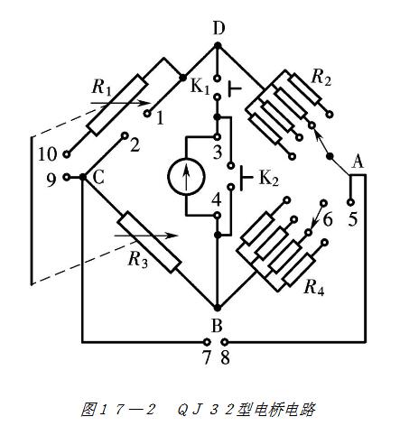
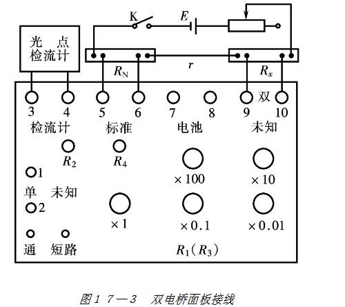
The form, structure and use of the double bridge are various, but the principle is the same. Figures 17-2 and 17-3 show the wiring diagram of the QJ32 type single and double bridge and the panel wiring diagram when it is used as a double bridge. Bridge level: 0.05; range: double bridge is 10-5 Ω ~ 102 Ω, single bridge is 50 Ω ~ 106 Ω; guaranteed accuracy level measurement range: 10-3 Ω ~ 105 Ω. External standard resistance RN = 0.01 Ω and RN = 0.001 Ω, 0.01 level. The indicator is an external AC15/2 galvanometer.
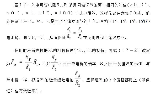
When the QJ32 type bridge is used as a double bridge, its indication error limit

Figure 7-14 shows the wiring diagram of the QJ32 type bridge used as a single bridge. Note that the "standard" terminals are shorted with a shorting. Adjust R3 (R1) to balance the bridge, then

The selection principle of the rate R2/R4 is also to ensure that all five knobs of the R3 are used.
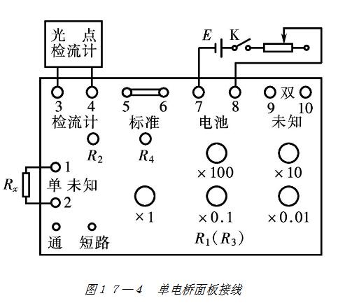
Two points should be noted during use: 1 After the initial value is selected, the “Turn†key on the panel should be opened and closed to observe the deflection of the cursor; 2 Pay attention to the correct use of the AC15/2 galvanometer. The adjustment of the bridge balance should start from the most insensitive x-stop of the galvanometer and gradually transition to the ×1 block.
Exterior Elevator,Outdoor Escalator,Escalator Outdoor,Outdoor Escalator Weatherproof Escalator
XI'AN TYPICAL ELEVATOR CO., LTD , https://www.chinaxiantypical.com