Foreword
All STM32 products have CRC peripherals that provide hardware support for CRC calculations, saving code space for applications. The CRC check value can be used to verify the correctness of data in data transmission, and can also be used for integrity check during data storage. In IEC 60335, the integrity of FLASH is also checked by CRC check. In the application of FLASH integrity check, the CRC check value of the entire FLASH (excluding the byte that last saved the CRC value) needs to be calculated in advance and placed at the end of the FLASH. In the process of starting or running the program, the same method is used to calculate the CRC check value of the entire FLASH, and then compared with the CRC value stored at the end of the FLASH.
EWARM supports the CRC calculation of the STM32 chip since v5.5. The process of calculating the CRC check value of the entire FLASH and saving it at the end of the FLASH can be done in the IAR. By configuring the CRC calculation parameters of EWARM, the CRC calculation is automatically performed on the entire FLASH space, and the calculation result is placed at the end of the FLASH. This article describes how to configure the CRC parameters of the IAR to be consistent with the CRC hardware module of the STM32. The examples in this article are based on STM32F072.
STM32 CRC peripheralsThe CRC check value is calculated by polynomial division, which can be implemented by XORing the divisor and the dividend. This method is very suitable for implementation through hardware circuits.
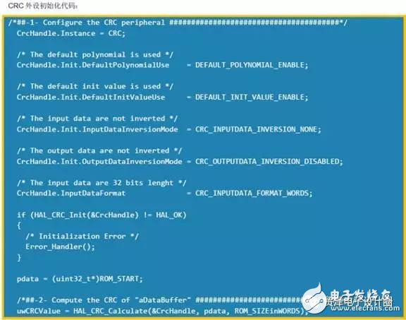
When using the STM32CRC peripheral, you should consider what CRC is used to generate the polynomial, the input data (the data to be verified), and the initial value.
Generating polynomial
The CRC32 polynomial is used by default: 0x4C11DB7

Some chips support programmable polynomials such as STM32F3, STM32F0, STM32L0
2. Initial value
The initial value of the CRC of STM32 defaults to 0xFFFFFFFF. The STM32F3, STM32F0, and STM32L0 series can modify the initial value.
3. Inversion of input/output data
The STM32F3, STM32F0, and STM32L0 series also provide the ability to invert the input/output data.
Bit inversion is not performed on input data and output data by default
• Bit inversion operations on input data can be set to operate in units of bytes/halfword/word. For example, the input data is 0x1A2B3C4D,
- Bitwise inversion in each byte, the result is 0x58D43CB2 - bitwise inversion in each halfword, the result is 0xD458B23C - bitwise inversion per word length, the result is 0xB23CD458
• Bit reversal of the output data.
- For example, the output data is 0x11223344, and the reverse is 0x22CC4488.
IAR CRC configuration1. Modify the Link file
Specify the storage location of the checksum in the FLASH, and add the following statement to the Link file.

This statement specifies that the value of the CRC is placed at the end of the FLASH. It is the end of the entire FLASH space, not the end of the application code. Thus, the position of the CRC value is fixed. It does not change with the size of the code.
2. Configure the parameters of the Checksum page.
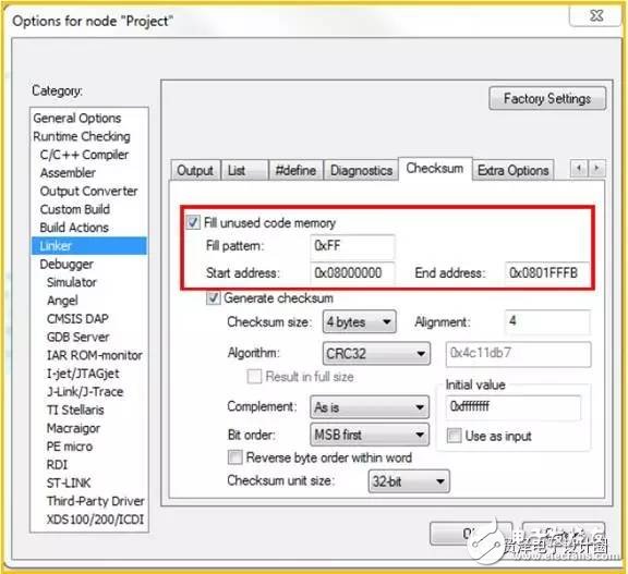
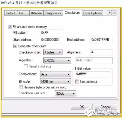
IAR Checksum page description (v6.4 and above)

The IAR checksum page is divided into two parts.
The first part, which is the part of the red coil. The range in which the CRC needs to be calculated and the free byte padding value are defined in the FLASH.
The rest is the setting part of the checksum calculation parameters.
Checksum size : Select the size of the checksum (bytes)
Alignment: Specifies the alignment of the checksum. If not filled, the default is 2 bytes aligned.
Algorithm: algorithm for selecting checksum
Complement: Whether a complement calculation is required. Selecting "Asis" means not making a complement calculation.
Bit order: The order of the bit outputs. MSB first, the high order of each byte is first. LSB first, the low order of each byte is first.
Reverse byte order within word: For the input data, the order of the individual bytes is reversed within one word.
Initial value: Initial value calculated by checksum
Checksum unit size: Select the size of the unit to be iterated, and iterate by 8-bit, 16-bit or 32-bit.
3.STM32 CRC peripherals use the default configuration IAR configuration
Configuration of the STM32CRC peripheral:
POLY= 0x4C11DB7 (CRC32)
Initial_Crc = 0Xffffffff
Input/output data is not inverted
Input data: 0x08000000~0x0801FFFB. (The last 4 bytes are used to put the calculated CRC value)


In the specific use, we can refer to the above description according to the actual application requirements to do the corresponding configuration.
Timer,Electronic Timer, Waterproof Timer, Countdown Timer
NINGBO COWELL ELECTRONICS & TECHNOLOGY CO., LTD , https://www.cowellsocket.com