Since the switching power supply is always in the cycle of opening and closing, this requires the devices in the switching power supply to have higher strength and shorter response time. Generally speaking, the working efficiency of the switching power supply is between tens of Khz and hundreds of Khz. In order to meet the frequent switching mode, the rectifier in the switching power supply has strict requirements on the Trr time. In theory, the general diode cannot be used, but the Schottky diode with ultra-fast recovery should be used.
If this is the case, can slow recovery diodes be used in switching power supplies? In fact, the reasonable use of slow recovery diodes in switching power supplies will get unexpected surprises. The following will illustrate with two examples of analysis.
Let's share with the netizens examples of the two work:
Case number one
The slow recovery power frequency rectifier 1N4007 is used to rectify the power supply winding of the main control IC to solve the problem of high bias voltage in multi-winding systems.
Using an IC as a 5-way output DVB power supply, during the mass production process, it was found that the defect rate was high, and the symptom was that the power supply did not work or hiccups. I went to the factory and found that the power supply voltage of the IC was too high, and the IC overvoltage protection mechanism was triggered.
As everyone knows, multi-output power supply, to achieve a good cross-regulation rate is quite a test of transformer design skills, biased power supply winding voltage is too high is inevitable. Customers have already produced more than 1W power supplies in batches, and redesigning the transformer is obviously not a good solution. The effect of increasing the resistance of the rectifier diode in series is also limited. After all, its main role is to filter out the peak voltage, and what causes the IC to protect the bias winding voltage is high. At this time, the charm of the slow rectifier is reflected. The final solution is to replace the fast recovery diode HER107 in the customer's original solution with 1N4007, and the problem is solved perfectly. See figure 1:
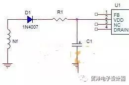
figure 1
Some people may ask, is there any hidden danger to slow use here? Is it appropriate?
Indeed, the slow rectifier of the switching power supply cannot be used, but it is indeed suitable here. Because the IC supply current is basically at the mA level and the load is not large, there will be no problem with the slow tube.
Case 2
The RCD absorption circuit in Flyback uses a slow tube 1N4007 to solve the problem of leakage inductance spike voltage stress and EMI radiation on the main switch.

figure 2
A common RCD absorption circuit structure is shown in Figure 2 (D1 generally uses fast recovery diodes).
If the transformer design is unreasonable and the leakage inductance is large, when the switch tube is off, the leakage inductance voltage is large and the oscillation time is long, resulting in a relatively large MOS voltage stress and excessive EMI radiation.
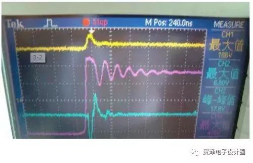
image 3
Figure 3 is the measured waveform of D1 using fast recovery diode UF4007.
The yellow line is the waveform of C1 in RCD, the pink is the drain waveform of the switch, and the blue is the voltage waveform of R1. Obviously the drain oscillation time is longer and the peak value is higher. What if you change D1 to a power frequency rectifier 1N4007?
The following is the performance of 1N4007:
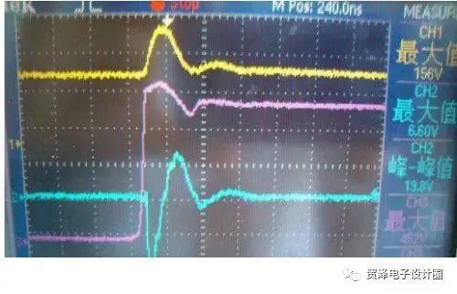
Figure 4
Obviously, the drain oscillation is perfectly suppressed, and the peak value is greatly reduced, thereby reducing the voltage stress of the MOS and greatly improving EMI.
Careful friends will find that the peak voltage of R1 becomes larger. Why is this? Because 1N4007 reverse recovery time is longer, so C1 electricity will flow back.
Some literature pointed out that it is this energy backflow that reduces the loss of R2, which will improve the efficiency of the power supply. However, after the actual measurement, no improvement in efficiency has been found, so I have reservations here.
Insufficient energy reflux actually exists, and the theoretical analysis and measured results have been shown. It is for this reason that 1N4007 heat will be relatively large, so this solution is suitable for low-power flyback, high-power is not recommended.
If in the design, encounter MOS voltage stress is relatively large and the total EMI exceeds the standard, you may wish to try this program.
Although in the daily switching power supply design, it is not recommended to use a slower response diode, but this does not mean that it is useless in the design. Such diodes can solve some difficult problems. So when you encounter problems in learning and design, it is better to think in another way, maybe the problem will be solved.
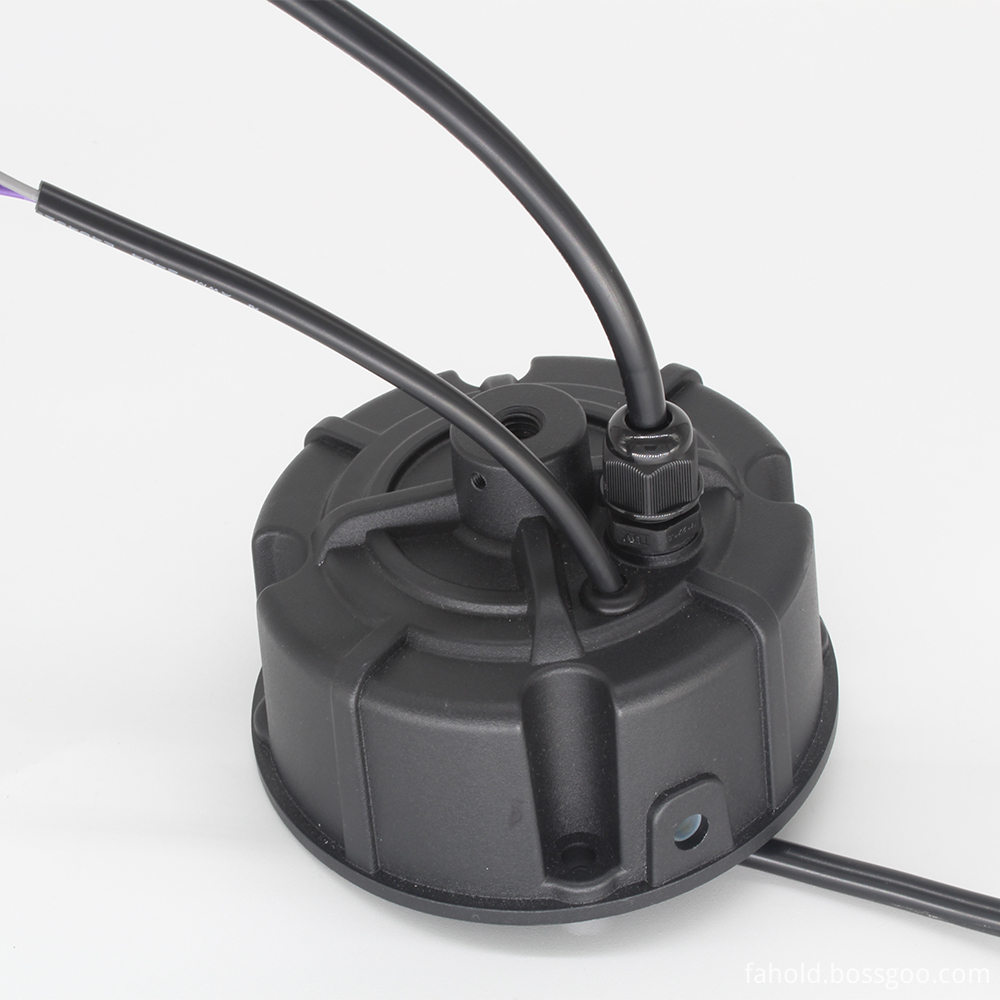
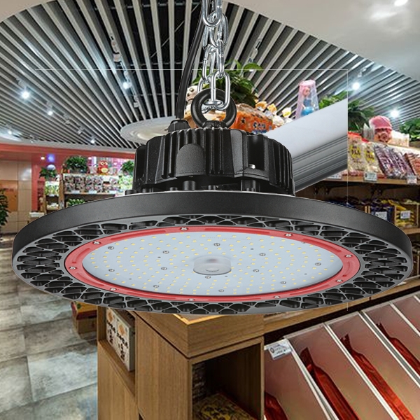
UFO High Bay Lights Led Driver
UFO High Bay Lights Led Driver
Constant current LED driver, UL dimmable transformer, With global manufacturing standards and various certifications including CE, UL and FCC, our lighting products are sold in domestic market and are exported to various international markets including US, UK, France, Germany, Australia, Africa, Korea etc. We offer a wide range of LED lighting solutions which includes LED Linear Lighting or System, , LED Lams, LED High bay lights etc. Maximize beauty of your workplace with our beautiful Warehouse Lighting, warehouse lights driver, Workshop Lighting, Supermarket Lighting and Factory lighting solutions.
Application: Specifically for high bay light,High Power Led Driver above 100W,normal for outdoor for waterproof, AC100-277V, 0-10V/PWM/RX dimming,short circuit protection,class 2 satety output design, passed the UL/FCC/TUV/RCM/CB/CE Certified. Europe and North America market.
Parameter:
Input voltage: 100-277vac
output voltage: 25-143vdc
current: 100mA-8000mA.
Power:108-240W
Power factor: >0.9
IP degree: IP65
Dimming:0-10V / PWM / RX / DALI.
>=50000hours, 5 years warranty.
certificate: UL CE FCC TUV SAA ect.
FAQ:
Question 1:Are you a factory or a trading company?
Answer: We are a factory.
Question 2: Payment term?
Answer: 30% TT deposit + 70% TT before shipment,50% TT deposit + 50% LC balance, Flexible payment
can be negotiated.
Question 3: What's the main business of Fahold?
Answer: Fahold focused on LED controllers and dimmers from 2010. We have 28 engineers who dedicated themselves to researching and developing LED controlling and dimming system.
Question 4: What Fahold will do if we have problems after receiving your products?
Answer: Our products have been strictly inspected before shipping. Once you receive the products you are not satisfied, please feel free to contact us in time, we will do our best to solve any of your problems with our good after-sale service.
Industrial High Bay Driver,Heat Resistant Ufo Led Driver,200W Led Driver
ShenZhen Fahold Electronic Limited , https://www.fahold.net