The CAN-bus bus is a bus communication method that connects all nodes through CANH and CANL to realize information channel sharing. While bringing wiring convenience and cost savings, it also increases the difficulty of on-site troubleshooting. Because all nodes are hooked together, it is difficult to quickly determine the faulty node once maintenance or communication failures are required. As shown in Figure 1.
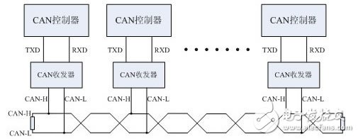
CANScope Analyzer Guangzhou Zhiyuan Electronics Co., Ltd. develops a comprehensive CAN bus development and testing professional tool, integrating mass storage oscilloscope, network analyzer, bit error rate analyzer, protocol analyzer and reliability test tool. And organically integrate and correlate various instruments; redefine the development and test methods of CAN bus, which can evaluate the correctness, reliability and rationality of CAN network communication in multiple angles; help users quickly locate faulty nodes and solve them. The various problems of CAN bus application are the ultimate tools for CAN bus development and testing.
CANScope's "Signal Quality" analysis plug-in can automatically analyze the waveforms sent by each CAN node, automatically reducing its minimum voltage amplitude, maximum voltage amplitude, signal amplitude, waveform rising edge time, waveform falling edge time, and signal time. Comprehensive "score", then visualize the signal quality of each CAN frame ID through a histogram. Users do not need to have a deep understanding of CAN bus protocol, eye diagram, slope, amplitude, ringing, ground bounce and other professional knowledge. Simply use CANScope for a period of time and then complete the analysis automatically with a click of the mouse. as shown in picture 2. Parameters evaluated for six measurements.
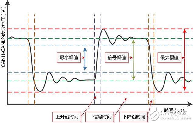
Figure 2 CANScope signal quality analysis parameters
As shown in Figure 3. For the actual test results of the CAN bus on a subway vehicle, the node with the frame ID of 0x308 can be seen by the ascending order of signal quality. The average signal quality is only 47 points, and the worst value is even 34 points.
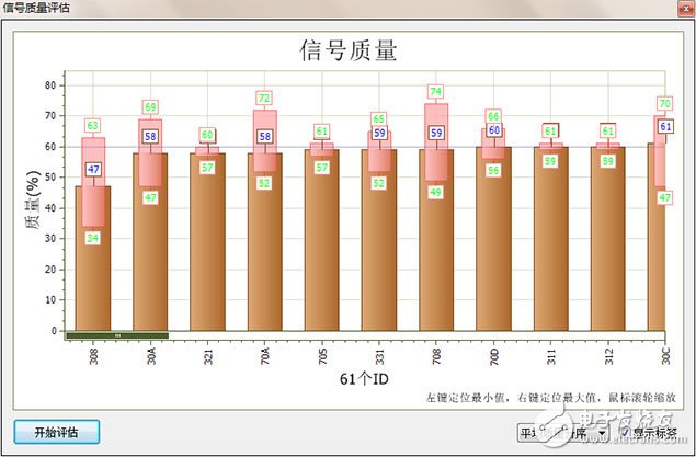
Figure 3 Schematic diagram of CANScope signal quality analysis (the worst quality on the left)
The right side of the signal quality evaluation map is the node with the best signal quality and 0x263 frame ID, and its worst quality is also 70 points. As shown in Figure 4,
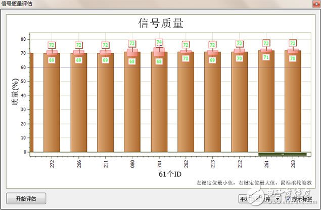
Figure 4 CANScope signal quality analysis diagram (the best quality on the right)
Looking at the waveform of 0x308 through CANScope's waveform filtering, it is found that there is a significant reflection "ground bounce" phenomenon, and the effective amplitude is relatively small. As shown in Figure 5,
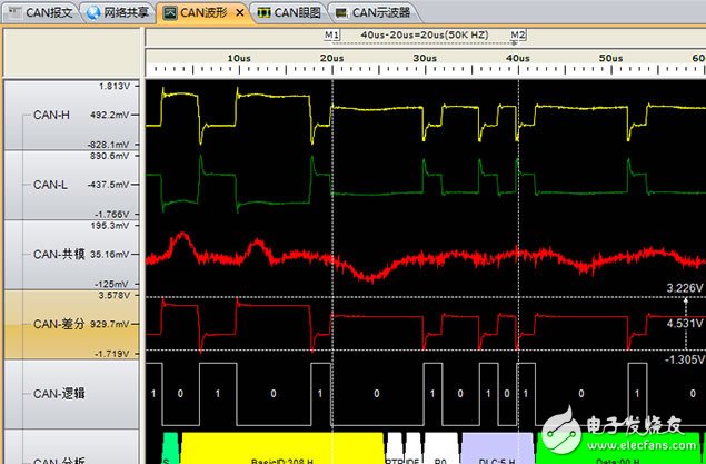
Figure 5 waveform with the worst signal quality
The waveform with the best signal quality of 0x263 is shown in Figure 6. There is no obvious reflection and the waveform is very neat. Therefore, it is necessary to remove the node that issued 0x308 for separate analysis.
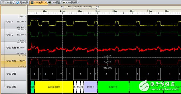
Figure 6 Waveform with the best signal quality
Laser Radar contains LSPD Safety Laser Scanner and LS laser radar. LSPD safety laser scanner is type 3 with CE certificate. It can be used for agv safety and industrial area protection. LS laser radar is for agv guide. Many famous agv manufacturers has installed LS laser radar to guide their agvs. Our cooperating brand contains Quicktron, Mushiny, Aresbots, etc. Feedback from customers are quite posotive.
Laser Radar
Laser Radar,Auto Guided Vehicle Guide Radar,Sick Laser Radar,Safety Scanner,Safety Laser Scanner,Ls Series Laser Radar
Jining KeLi Photoelectronic Industrial Co.,Ltd , https://www.sdkelien.com