The read/write distance of RFID readers depends on many factors, such as the RFID reader's transmit power, the reader's antenna gain, the reader's IC's sensitivity, the reader's overall antenna efficiency, and the surrounding Radio frequency (RF) interference from objects (especially metal objects) and other external transmitters from nearby RFID readers or similar wireless phones.
Calculate power densityThe power density of the RF electromagnetic wave emitted by the read/write antenna is calculated as shown in Equation 1. Among them, Sr = power density, Pt = transmit power of read-write antenna, Gt = gain of read-write antenna, R = transmit distance of read-write antenna.
Sr = PtGt/4Ï€R2--------------------------------------------- --Formula 1
From Formula 1, it can be seen that the power density is inversely proportional to the square of the distance. In an ideal case, this formula is valid, for example, in the absence of an object that attenuates the RF signal, an external transmitter that may cause interference, and a microwave darkroom where the same signal source produces multipath effects of other interference modes. The following will discuss these factors in more detail.
Consider antenna gainThe antenna gain is given in dBi, where dBi represents the forward gain of an antenna compared to a hypothetical isotropic antenna (hypothetical isotropic antenna); it is assumed that the isotropic antenna will distribute the energy evenly in all directions. When designing the structure of the antenna, it should have more radiant energy in one direction than in the other, resulting in higher gain. Taking the sprinkler head as an example, it is possible to have a deeper understanding of this, such as concentrated injection, narrowing of the water flow, and increase of the water injection distance, which is similar to increasing the antenna gain, that is, concentrated energy radiation in a certain direction.
Pay attention to antenna 3dB beam width and half power pointTo improve the reader's read/write distance, another important antenna characteristic must be considered, namely the 3dB beamwidth pattern generated by the antenna. The 3dB beamwidth shown in Figure 1 contains 75% of RF energy. In this range, the reader has the best read and write performance. The 3dB beam width depends on the antenna gain. For example, the higher the antenna gain, the more concentrated the energy and the narrower the 3dB beamwidth.
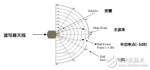
Figure 1 3dB beamwidth generated by the antenna
The 3dB beamwidth can also be used to describe the half-power point of the beam, ie, where the RF energy is reduced to half. In addition, Figure 1 also shows side lobes that most antennas will exhibit. The reader can read and write in this direction, but its reading and writing distance will be greatly reduced.
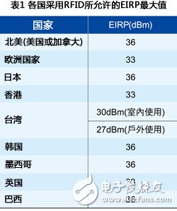
Optimize the reader's reading and writing distanceIn order to maximize the read/write distance of the RFID reader, the following techniques should be considered. First, the effective isotropic radiated power (EIRP) is referred to as the highest under the emission regulations for the specified area. For example, Section 15.247 of the Federal Communications Commission (FCC) states that the maximum allowed by the EIRP is 4 watts (W) (36 dBm). This means that with a 9dBiL antenna, the power delivered by the RFID reader to the antenna, including cable losses, must not exceed 27dBm. On the other hand, for a 6dBiL antenna, the transmission power must not exceed 30dBm. Table 1 lists the maximum allowable EIRP for countries using RFID.
An important characteristic related to the antenna gain for the RF signal transmitted at the same point in front of the reader antenna (orbit axis) is a circularly polarized antenna 9dBiC similar to the linearly polarized antenna 6dBiL. . This is because the linearly polarized antenna combines the x and y components of the electric field component on the same axis, thereby increasing the energy by 3 dB (~29%) in this particular direction.
However, linearly polarized antennas do not allow reader/writer orientation flexibility. In other words, the reader must point in the same direction as the read and write antenna polarization, otherwise the reader will not receive energy.
On the other hand, circularly polarized antennas have two electric fields that are 90 degrees apart (Figure 2). Therefore, energy is distributed between two mutually orthogonal axes, each containing less than 3 dB of energy compared to the linearly polarized RF signal propagating in free space.
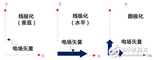
Figure 2 The circularly polarized antenna has two electric field components that are 90 degrees apart from each other
In this case, the advantage is that the reader does not have any restrictions with respect to the direction of the antenna. This means that the reader can be turned in any direction and the received energy is basically the same. The disadvantage is that the energy transmitted by each antenna of the interrogation antenna is reduced by 3dB compared with the linear polarization system. The choice of linearly or circularly polarized antennas depends on the application.
Second, it is very important to clear all objects in the vicinity of the antenna and the reader. The direction of the line of sight between the antenna and the reader must be free of obstructions. If all objects are removed without any obstruction in the line of sight, the free space loss (FSL) of RF electromagnetic waves can be calculated by Equation 2, where r = distance to the reader and λ = EM wavelength.
FSL = 20Log(4πr/λ)------------------------------------------ -----Formula 2
The RF electromagnetic wave passes through an object with a dielectric constant exceeding 1.0 (ε) 1.0, such as wood, plastic, or rubber material. According to Formula 2, the FSL is approximately 36 dB. Due to the attenuation of the propagation of the RF signal, the read/write distance of the reader is also significantly shortened.
In addition, surrounding objects can cause "multipath effects" in the RF signal, resulting in zero and amplitude RF energy oscillations in the RF field (Figure 3). Figure 3 shows both constructive (in-phase) and destructive (out-of-phase) incident waves. The two kinds of incident waves of the same length can increase the energy of a specific area by about 3dB, and significantly extend the read/write distance of the reader/writer.
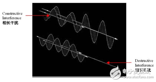
Fig. 3 Schematic diagram of constructive (in-phase) and destructive (out-of-phase) incident waves
On the other hand, destructive interference causes the two incident RF electromagnetic waves to cancel each other, and the resulting area will become a “zeroâ€, which will present insufficient energy when the reader/writer is activated. This is a typical RFID environment.
Furthermore, if there is a spectrum analyzer along a linearly polarized antenna, RF measurements should be made to see if there is an external transmitter that interferes with the reader's RF electromagnetic wave and affects the reader's energy level. If there are external transmitters and the RF channels of these transmitters are within the operating frequency range of the RFID interrogator, this may significantly shorten the read/write distance of the reader. External transmitters refer to wireless phones and other nearby RFID readers.
Some countries, such as the United States, require all FCC 15.247 certified readers to use Frequency Hopping Spread Spectrum (FHSS) technology. Under this configuration, the reader pseudo-randomly "jumps" on all its fifty channels, with a maximum dwell time of 400 milliseconds (ms) per channel. This helps to reduce the amount of interference that RFID readers transmit to their surroundings and reduce the amount of interference they receive.
In general, when the channel of the external transmitter and the reader are in the same frequency band, when the intensity of any channel is greater than -30dBm, it must be processed. The following measures can be taken: locating the interference source, determining whether it can be turned off, or reducing its transmission power; shielding with a certain metal piece or object to avoid the influence of external transmitters; keeping the RFID device away from the external transmitter; will read The write antenna points away from the external transmitter; ensure that the maximum EIRP allowed by the power transmission limits of the area where the read/write system (RFID reader and interrogator antenna) is located; set the software to prevent the RF channel on which the external transmitter is located from reading and writing In the frequency range of the instrument.
In addition, the reader sensitivity varies with the RFIC model. Therefore, readers with lower sensitivity have shorter read/write distances than readers with higher sensitivity. However, in some cases, high sensitivity RFICs are not prioritized. For example, in a supply chain application, using a portable RFID reader to monitor inventory does not require a particularly long read/write distance. For applications such as Electronic Vehicle Registration (EVR) and Electronic Vehicle Identification (EVI), it is necessary to have a longer read/write distance, and therefore higher sensitivity is required. So the size of the sensitivity needs to be related to the specific application.
Finally, the reader antenna efficiency is another factor that affects the read/write distance of the reader. Antenna designs that match the input impedance of the reader IC can improve overall efficiency and achieve greater read and write distances. The RFIC input impedance is generally found in its corresponding data sheet.
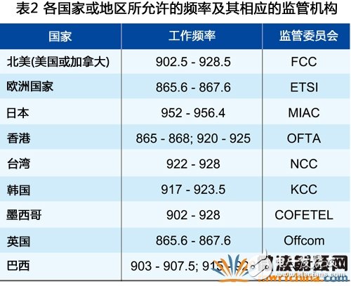
The reader antenna design should be properly matched to the input impedance of the data sheet. In general, this means adjusting the antenna to the center frequency of the desired frequency band. This band depends on the area where the reader is used. Table 2 lists the allowed frequencies and corresponding regulatory agencies in some countries and regions.
French Power Strip,Surge Protector Power Strip,Power Strip With Flat Plug,Overload Protector Power Strip
CIXI KYFEN ELECTRONICS CO.,LTD, , https://www.kyfengroup.com