Weekend times are always so easy
Don't talk about technology with your friends today
Let us work together to create a gift for a dedicated engineer
= Preliminary preparation: This power supply is required to provide four voltage levels according to the requirements, wherein: +5V, -5V, +36V is one way; +12V is the other way. Among them, +5V is mainly used for the SCM used in the following lines, and the current is 1A; -5V is used by some op amp ICs that require dual voltage supply, and the current is 0.5A; +36V is used by subsequent devices for a certain detection function, and the current is only 0.1A. . The other way +12V is to provide power for the DC12V relay used in the follow-up line, the current is 0.5A
= Start to focus
First, according to the actual situation of the user, it is finally determined that the AC90-265V power supply environment can meet the actual needs. At the beginning, I intended to use the UC38 series IC as a design blueprint for a simple replacement design. I could consider other factors such as cost factors and technical support, and I gave up the idea. In the end, I personally decided to design the IC based on A6252, a popular IC that was more than a decade ago. A6252 is a product of Japan Sanken Electronics Co., Ltd. It was widely used in CRT TVs and other household appliances.
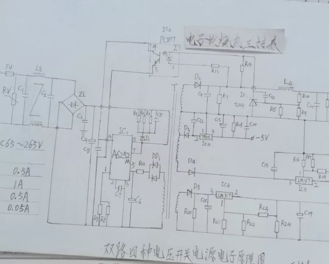
Figure 1 is my hand-painted schematic diagram of the power supply line, due to cost constraints on my post-stage -5V, +12V using three-terminal integrated voltage regulator IC regulator; taking into account the actual situation of +36V, I use three-terminal adjustable stability Pressure tube LM317L (current 0.5A) for voltage regulation and other aspects of processing. Because of the quality of +5V power supply, it largely determines the stability of the follow-up line work, so I use TL431 and PC817 this "golden partner" to implement "VIP" level processing.
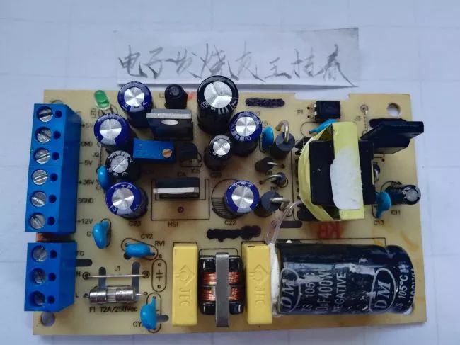
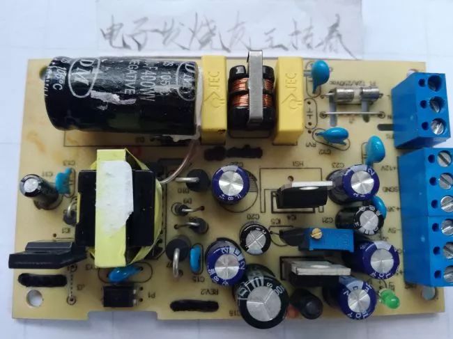
The two figures above show the finished circuit board. The output and input follow the principle of left-low-right-high. From the chart, it should be easy to see that I have done my best to limit EMI, overvoltage, overcurrent protection, and other requirements related to power supply hardware requirements at a limited cost.
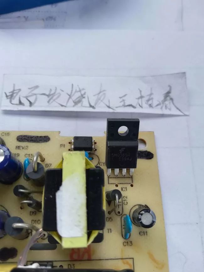
This close-up is the "male one" of the power supply, the A6252. This is a four-pin package and is available in 8-pin packages in some products.
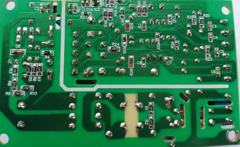
The last display is the PCB on the back of the power supply. Please pay attention to the partitions opened in the board. As for the reason, I think I would like to listen to the opinions of the altarists. The white line is framed by the low pressure section, which is easy to distinguish between high and low pressures. It can also serve as a reminder for maintenance.
â—High-efficiency, energy-saving design, full display of green concept from inside to outside
The system adopts a high-efficiency rectifier, the peak efficiency of the rectifier is greater than 96.2%, and the power consumption of the rectifier sleep is as low as 4W or less.
â—The rectifier module is small in size and high in power density, improving the utilization of cabinet space
â—Fully digital design, more stable performance
The rectifier adopts DSP+MCU dual digital circuit control mode, the system adopts CAN+RS485 dual bus control, the system power supply reliability is higher, and the transmission rate is faster.
High efficiency rectifier
Changzhou Changyuan Electronic Co., Ltd. , https://www.cydiode.com