This paper introduces a 32-bit control core based on the Cortex-M3 core, an external controllable constant current source circuit and a color sensor to form a simple characteristic test device. The structure is simple, the cost is low, and there are research on LED characteristics. Higher practical value.
1 Introduction
LED (Light-EMItting-Diode), which is a new generation of illumination source, is gradually replacing traditional incandescent lamps and fluorescent lamps with its advantages of high efficiency, energy saving, environmental protection, long life and high reliability. All governments have vigorously supported the development of white LEDs, and the developed countries such as the United States, Japan, and the European Union have been actively promoted by the government. With the expansion of the application range of LEDs, users have higher requirements on product quality. They not only require uniform optical characteristics such as brightness and wavelength, but also have strict requirements on their forward operating voltage and current characteristics. Therefore, it is of great significance to study the test instrument of LED photoelectric parameters to improve product quality and reduce production cost.
The special LED photoelectric characteristic test equipment has complex structure, especially the optical characteristic test uses spectrometer, photometer, etc. Although the instrument has the characteristics of high precision, it still has complex structure, high cost, large volume, and is not portable or used. Convenience, limited system stability and other shortcomings, so this instrument can only stay in large-scale analysis and testing experiments, the application range is difficult to expand.
The development of a small-volume, low-price, low-precision LED photo-electric measuring instrument that meets the general requirements has become a trend in the development of instruments.
Although the photoelectric characteristics of LEDs are many, for most users, the main concern is the volt-ampere characteristics of LEDs and the relationship between LED brightness and current. Therefore, the system designed in this paper is mainly to test these two parameters, and pass Simple hardware and software expansion, can also test the LED color temperature, dominant wavelength, light intensity distribution and other parameters, for LED characteristics research and drive circuit design and other application development.
2. System principle and composition
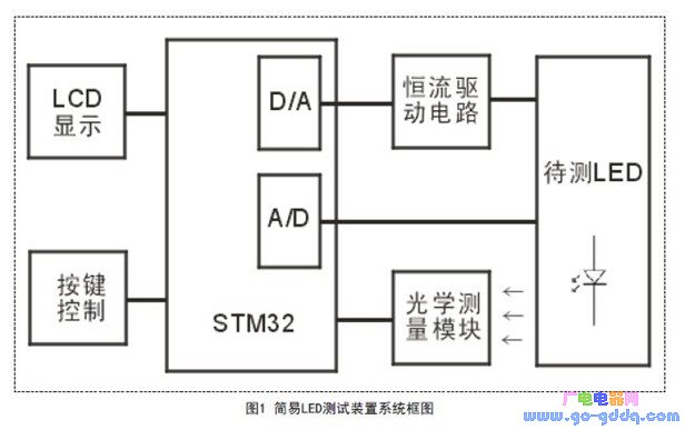
The whole system is mainly composed of STM32 microprocessor, optical measurement module, constant current drive module, LCD liquid crystal display module, button control module, etc., as shown in Figure 1.

The STM32 microprocessor is controlled by a touch screen or a touch screen on the LCD. The internal D/A converter generates a control voltage that controls the external constant current driving circuit to generate a constant current required for LED operation to be applied to the LED to be tested. The generated voltage drop is collected by the A/D converter inside the STM32 after the signal amplification adjustment circuit, thereby measuring the volt-ampere characteristics of the LED. In addition, the light emitted by the LED is measured by the optical measuring module to be converted into a digital signal, which is collected and processed by the STM32, thereby measuring optical characteristics such as the brightness of the LED.
2.1 STM32 microprocessor
The microprocessor is the core of the whole control system. It controls the current set by the constant current drive circuit, collects the voltage of the LED, measures the data of the optical measurement module, performs data processing, control algorithm operation, display control, and the like. In order to ensure the practicability and scalability of the system, the control system adopts the "enhanced" series STM32F103RCT6 from STMicroelectronics, 32-bit ARM Cortex-M3 core, working frequency up to 72MHz, built-in high-speed memory (up to 128K bytes) Flash and 20K bytes of SRAM), rich enhancement I/O ports and peripherals connected to two APB buses, 16 12-bit ADCs and 2 12-bit DACs, 3 general-purpose 16-bit timers and A PWM timer also includes standard and advanced communication interfaces: up to 2 I2C and SPI, 3 USART, one USB and one CAN, meeting the requirements in terms of storage capacity and speed. In this design, the STM32's own ADC and DAC modules are used, which greatly reduces system cost.
2.2 constant current drive circuit
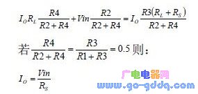
The core of the constant current drive circuit is the V / I conversion circuit. As shown in Figure 2, Vin is the voltage of the internal D/A output of STM32, RL is the load, that is, the LED to be tested, and Rs is the current sampling resistor for controlling the output. The magnitude of the current, U1 is a high power operational amplifier.

It can be seen from Fig. 2 that if the resistors R1 and R2 are much larger than Rs and RL, they are ideally available.

It can be seen from Equation 2 that the output current is independent of the load. In the case of the fixed sampling resistor Rs, the output current is proportional to the input control voltage. However, in the application, it should be noted that the two input resistors R3 and R4 and the two feedback resistors R1 and R2 must be strictly matched, otherwise a large error will result. Rs also uses precision power resistors. In addition, compensation calibration can be done in the software during system debugging to ensure output current accuracy.
The op amp OPA548 in Figure 2 is a high-voltage, high-current power op amp with excellent small-signal amplification that is ideal for driving multiple loads. The power supply voltage (+VS~-VS) is 60V, which can work with single or dual power supply. The input impedance is high and the bias current is small. Continuous output of 3A high current (peak current up to 5A), and internal over-temperature and current overload protection, users can carry out precise current limiting design according to requirements 2.3 Optical measurement module
In this design, the new color sensor TCS3200 is used to measure the optical characteristics of the LED, and the brightness of the three primary colors contained in the LED illumination can be simultaneously measured. The TCS3200 is a programmable color light to frequency converter from TAOS. It integrates configurable silicon photodiodes with current-to-frequency converters in a single CMOS circuit, while integrating red, green and blue (RGB) filters on a single chip, making it the industry's first digital-compatible interface. RGB color sensor.
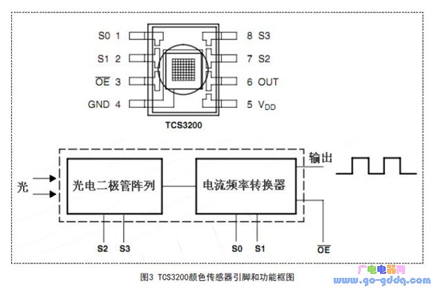
The TCS3200's output signal is digital and can drive standard TTL or CMOS logic inputs, so it can be directly connected to a microprocessor or other logic circuit. Since the output is digital and can achieve conversion accuracy of more than 10 bits per color channel, the A/D conversion circuit is no longer needed, making the circuit simpler. Figure 3 shows the pin and functional block diagram of the TCS3200.

When incident light is projected onto the TCS3200, different filters can be selected by different combinations of photodiode control pins S2 and S3; square waves of different frequencies are output after current to frequency converter (duty cycle is 50%) Different colors and light intensity correspond to square waves of different frequencies; the output scaling range can be adjusted by outputting scaling control pins S0 and S1 to adjust different output scaling factors to suit different needs.
Because STM32 operates at a higher frequency, S0 and S1 are directly connected to a high potential, so that the output scale factor is 100%. S2 and S3 are controlled by the STM32 pin, and the color sensor output signal is programmed with STM32 to achieve frequency measurement.
3. Measurement data calculation and processing
STM32 software system design mainly includes liquid crystal display, button processing, DAC control, ADC control, color sensor control and counting measurement. These modules are relatively simple and will not be described here. The following mainly introduces the data operation of LED optical characteristic measurement. And processing procedures.
The quantitative measurement of the color of an object is a complex problem involving many factors such as the observer's visual physiology, visual psychology, lighting conditions, and observation conditions. CIE (International Commission on Illumination) has published a series of colorimetric systems since 1931, which stipulates a set of principles, data and calculation methods for color measurement, forming a CIE standard colorimetric system that lays the foundation for modern colorimetry.
According to the CIE recommendation, the chromaticity of the source can be characterized by tristimulus values ​​X, Y, Z and chromaticity coordinate color systems.
You can convert RGB values ​​to XYZ values ​​using the following formula: 
The relationship between chromaticity coordinates and tristimulus values ​​is:

The color sensor TCS3200 measures the proportion of the three primary colors that constitute the chromaticity of the light source, and obtains the R, G, and B values. After calculation, the tristimulus values ​​X, Y, Z and chromaticity coordinates x, y, z of the chromaticity of the light source can be obtained. With the chromaticity coordinates, the brightness, main wavelength, color purity, and correlated color temperature of the light source can be obtained according to the CIE1931 standard chromaticity system. The Y value in Equation 3 corresponds to the response to brightness in the human eye and can be used to calculate the luminance of the LED.
There are many methods for obtaining the correlated color temperature (CCT, Correlated Color Temperature) from the chromaticity coordinates. The approximate formula method is simple and easy to implement, and the accuracy can also meet the general requirements. When 3000K

4. Experimental results
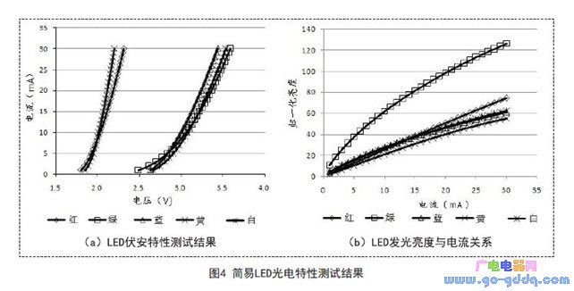
Using the above circuit, a simple LED photoelectric characteristic test device was designed and tested with some red, green, yellow, blue and white LEDs. The results are shown in Fig. 4. Fig. 4(a) shows the volt-ampere characteristics of different color LEDs. Curve, Figure 4 (b) shows the relationship between the brightness of the LEDs of different colors and the current. As can be seen from the figure, the LED current changes rapidly with voltage, and the luminance and current are basically linear. This can be used as a reference for designing LED driver circuits. In addition, the volt-ampere characteristics were calibrated using a Keithley 2612 high-precision source meter, and the brightness test was calibrated with an illuminometer. The experimental results show that the result error can be controlled within 5% through hardware adjustment and software compensation, achieving practical goals.

5. Conclusion
In this paper, the STM32 microprocessor is used as the core, and the color sensor is the main component. A simple LED photoelectric characteristic device is designed to test the LED characteristics such as volt-ampere characteristics, luminous intensity, correlated color temperature and dominant wavelength of the LED. The whole system is simple, intelligent and low-cost, and can replace special equipment such as expensive spectrum analyzers in some LED research and application fields. The experimental results show that the test accuracy meets the practical requirements, and the scheme is feasible.
A manual pulse generator (MPG) is a device normally associated with computer numerically controlled machinery or other devices involved in positioning. It usually consists of a rotating knob that generates electrical pulses that are sent to an equipment controller. The controller will then move the piece of equipment a predetermined distance for each pulse.
The CNC handheld controller MPG Pendant with x1, x10, x100 selectable. It is equipped with our popular machined MPG unit, 4,5,6 axis and scale selector, emergency stop and reset button.
Manual Pulse Generator,Handwheel MPG CNC,Electric Pulse Generator,Signal Pulse Generator
Jilin Lander Intelligent Technology Co., Ltd , https://www.landerintelligent.com