introduction
LED dot matrix display is a new display mode integrating microelectronics technology, computer technology and information processing. Because of its long life, wide dynamic range, stable and reliable operation, low power consumption and fast time response, it has become the leader in many display media and is an ideal choice for outdoor work display. Using the CH451 chip to drive the LED dot matrix has the following characteristics: fast speed, low power consumption, dynamic display scan control, direct drive 64-bit LED dot matrix, software can control the brightness of the LED to reduce power consumption. The CH451 can exchange data with a controller such as a microcontroller through a 1-wire or a 4-wire serial interface that can be cascaded. The serial interface of the CH451 is implemented by hardware. The controller can frequently operate at high speed through the serial interface without absolutely reducing the efficiency of the CH451. The circuit designed by it not only has simple design of software and hardware, but also has low power consumption, fast response speed, strong driving capability and less I/O port line. It is a cost-effective and flexible application design.
1 Instructions for use of CH451
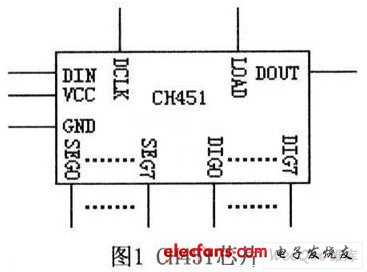
The CH451 has eight 8-bit data registers for storing eight word data, corresponding to eight groups of eight LEDs driven by CH451, and supports word data in the data register to shift left and right. Left loop, right loop, and support independent flashing control of each digital tube, the properties of the flicker control are not affected during the left or right movement of the word data or the left and right cyclic movement. The CH451 has a hardware-implemented high-speed 4-wire serial interface that includes four signal lines: a serial data input line DlN, a serial data clock line DCLK, a serial data load line LOAD, and a serial data output line DOUT. DIN is used to provide serial data, high level means bit data 1, low level means bit data 0, serial data input order is low order first and high order first. DCLK is used to provide the serial clock. The CH451 inputs data from DIN on its rising edge and outputs data from DOUT on its falling edge. The CH451 has a 12-bit shift register. On the rising edge of DCLK, the bit data on DIN is shifted into the highest register of the shift register, and so on. The original lower data is shifted into the lowest register, after the rising edge. A falling edge, the original low-order data is output from DOUT. The CH451 allows the serial clock frequency of the DCLK pin to be greater than 10MHz, enabling high-speed serial input and output. LOAD is used to load serial data, and CH451 loads the 12-bit data in the shift register on its rising edge and analyzes and processes it as an operation command. CH451 can dynamically drive 8&TImes;8 LED dot matrix. All the columns of the dot matrix are connected to the column drive pins SEGO~SEG7 of CH451 through the series connected current limiting resistor R1. All the rows of the dot matrix are respectively DIG0~DIG7 pins of CH451. Drive. The larger the resistance of the series current limiting resistor R1 is, the smaller the segment driving current is. The lower the display brightness of the digital tube, the resistance value of R1 is generally between 60Ω and 400Ω. Under other conditions, the priority should be preferred. Large resistance.

2 software and hardware design examples
2.1 hardware circuit
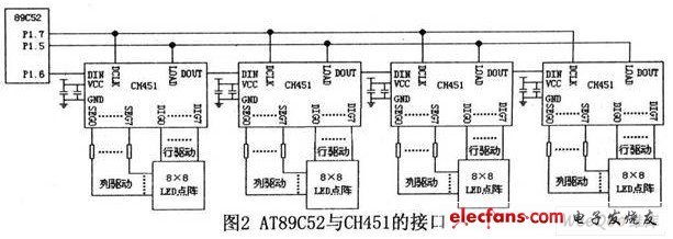
Figure 2 shows the display panel circuit designed with the interface of AT89C52 and CH45l.

P1.5, P1.6, and P1.7 of Pl port are used to control the display of LED dot matrix, which are respectively connected to LOAD, DIN and DCLK pins. 4 8 & TImes; 8 LED array composed of 16 & TImes; 16 dot matrix module, if you want to display a Chinese character, just send 32 bytes of dot matrix data to the CH451 through 8 48-bit load word data commands. Because it is 4 CH451 cascades, each operation command must be 48-bit data. Finally, the rising edge of the LOAD signal line output informs all CH451 to load the respective command data.
2.2 Display Driver
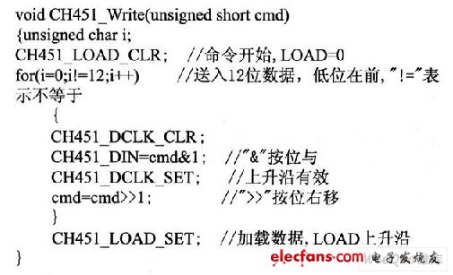
Define the array to store the display data. After the CPU resets, call the CH451 Write function to write commands and data operations to the CH451.
Write 12bit control word function:

3 Conclusion
It can be seen from the above examples that the design of LED dot matrix driver circuit with CH45l has no complicated technical problems in hardware and software design, especially software design. This is a solution when the I/O line is tight. Has a very good price/performance ratio. (
Aluminum Miniature Load Cells,Miniature Load Cells,Miniature Load Cell Sensor,Subminiature Load Cells
Xiaogan Yueneng Electronic Technology Co., Ltd. , https://www.xyeloadcell.com