The servo system, also known as the servo system, is an automatic control system that can track the input command signals to obtain accurate position, velocity or force output. Most servo systems have a detection feedback loop, so the servo system is a feedback control system. According to the feedback control theory, the servo system needs to continuously detect the change of the output of the controlled object under various disturbance actions, compare it with the command value, and automatically adjust the system with the deviation values ​​of the two to eliminate the deviation and make the controlled object. The output always tracks the input command value.
The servo system is operated in accordance with the deviation between the input command value and the physical quantity of the output. Therefore, the working process of the servo system is a dynamic transition process in which deviations are continuously generated and continuously eliminated.
Examples of servo control can be seen everywhere. For example, when a worker operates a machine tool for processing, the eye must always observe the progress of the process. The feedback information from the eye is processed by the brain to determine how to operate in the next step, and then the hand wheel is shaken by hand. Drive the workpiece or tool on the workbench to perform brain decisions, eliminate deviations during machining, and finally machine the workpieces that meet the requirements. In this example, functions such as detection, feedback, and control are implemented by humans, and in the servo system, these functions are implemented by sensors, control, and information processing devices. In the servo system of CNC machine tools, position detection sensors, numerical control devices and servo motors replace the functions of human eyes, brain and hands, respectively.
Many mechatronic products (such as CNC machine tools, industrial robots, etc.) need to track and control the output. Therefore, the servo system is an important part of mechatronics products, and is often the main body to achieve the functions of certain products. The servo system is inseparable from the comprehensive application of mechanical technology and electronic technology. Its function is realized through electromechanical combination. Therefore, the servo system itself is a typical mechatronic system.
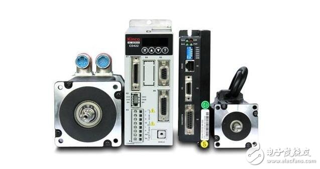
Classified by regulation theory
Open loop servo system
The open loop servo system is a system without position feedback, and its driving components are mainly power stepping motors or hydraulic pulse motors. The essence of the working principle of these two kinds of driving components is the digital pulse-to-angle displacement transformation, which does not use the position detecting component to achieve positioning, but relies on the driving device itself, the angle of rotation is proportional to the number of command pulses; The frequency of the pulse is determined.
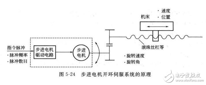
The open-loop servo system has a simple structure and is easy to control, but the accuracy is poor, the low speed is not stable, and the torque is small. Generally used for light load changes or economical CNC machine tools.
2. Closed loop servo system
The closed-loop servo system is an error-controlled follow-up servo system. The error of the CNC machine feed system is the difference between the position command of the CNC output and the actual position of the machine table (or tool holder). The closed-loop system motion actuator does not reflect the position of the motion and therefore requires a position detection device. The device measures the actual displacement or the actual position, and feeds the measured value back to the CNC device, compares it with the command, and obtains the error, which in turn constitutes closed-loop position control.
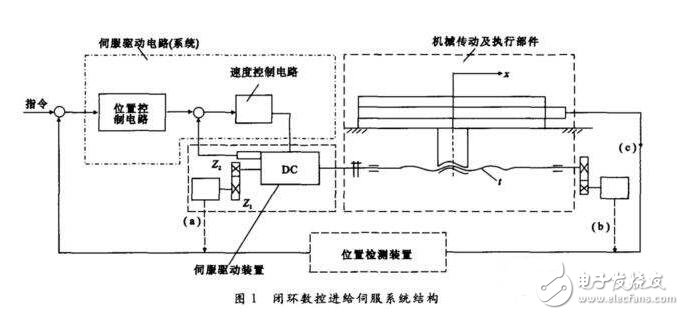
Since the closed-loop servo system is feedback control, the feedback measuring device has high precision, so the error of the system transmission chain, the error of each component in the ring and the error caused by the motion can be compensated, thereby greatly improving the following accuracy and positioning accuracy.
3. Semi-closed loop system
The position detecting element is not directly mounted on the final moving part of the feed coordinate, but is instead converted by a position of the mechanical transmission part, which is called indirect measurement. That is to say, part of the transmission chain of the coordinate motion is outside the position closed loop, and the transmission error outside the loop is not compensated by the system, so the accuracy of the servo system is lower than that of the closed loop system.
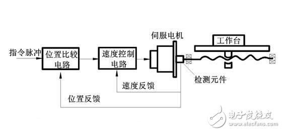
The control structure of the semi-closed loop and the closed loop system is consistent. The only difference is that the closed loop system loop includes more mechanical transmission components, and the transmission error can be compensated. In theory, the accuracy can be very high. However, due to mechanical deformation, temperature changes, vibration and other factors, system stability is difficult to adjust. In addition, after the machine has been running for a period of time, the stability of the system changes and the accuracy changes due to the wear, deformation and other factors of the mechanical transmission components. Therefore, there are many semi-closed loop systems currently in use. The full-closed servo system is only used on high-precision CNC machine tools with high transmission parts, stable performance, and little change in temperature during use.
Classification by using DC servo motor and AC servo motor
1. DC servo system
The servo motors commonly used in DC servo systems are small inertia DC servo motors and permanent magnet DC servo motors (also known as large inertia wide speed DC servo motors). The small inertia servo motor minimizes the moment of inertia of the armature, so the best speed is obtained. Small inertia servo motors are generally designed to have high rated speed and low inertia, so when applied, they must be connected to the lead screw through an intermediate mechanical drive (such as a gear pair).
2. AC servo system
The AC servo system uses an AC asynchronous servo motor and a permanent magnet synchronous servo motor. Due to the inherent lap point of the DC servo motor, its application environment is limited. The AC servo motor does not have these disadvantages, and the rotor inertia is smaller than that of the Dc Motor, making the dynamic response good. In addition, under the same volume conditions, the output power of the AC motor can be increased by 10% to 70% compared with the DC motor. Also, the capacity of the AC motor can be made larger than that of the DC motor to achieve higher speed and voltage.
Classification by feed drive and spindle drive
Feed servo system
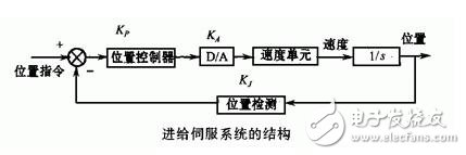
The feed servo system refers to a general concept servo system, which includes a speed control loop and a position control loop. The feed servo system completes the feed motion of each coordinate axis and has positioning and contour tracking functions.
2. Spindle servo system
Strictly speaking, the general spindle control is just a speed control system. It mainly realizes the rotary motion of the main shaft, provides the torque and power during the cutting process, and ensures the adjustment of the arbitrary speed to complete the infinitely variable speed in the speed range. The spindle with C-axis control is a general-purpose position servo control system, like the feed servo system.
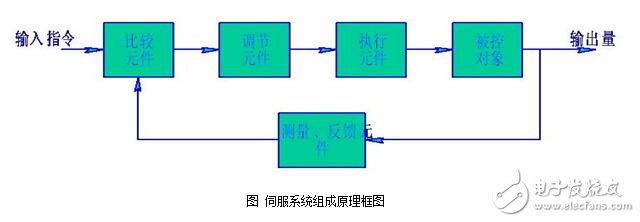
Structure of the servo systemThe structure and type of mechatronics servo control system are numerous, but from the perspective of automatic control theory, servo control system generally includes five parts: controller, controlled object, execution link, detection link and comparison link. The following figure shows the block diagram of the servo system components.
Comparison link
The comparison step is a process of comparing the input command signal with the feedback signal of the system to obtain a deviation signal between the output and the input, which is usually implemented by a special circuit or a computer. ?
2. Controller
The controller is usually a computer or PID control circuit whose main task is to transform the deviation signal output by the comparison component to control the actuator to act as required.
3. Execution
The function of the execution link is to convert the various forms of input energy into mechanical energy according to the requirements of the control signal, and drive the controlled object to work. Actuators in mechatronic systems generally refer to various motors or hydraulic and pneumatic servos.
4. Controlled object
5. Testing
The detection link is a device that can measure the output and convert it into the dimensions required for the comparison, typically including sensors and conversion circuits.
Technical requirements for servo systemsSystem accuracy
Servo system accuracy refers to the accuracy of the output of the output signal, and it is expressed in the form of error. It can be summarized as dynamic error, steady-state error and static error.
2. Stability
The stability of the servo system refers to the ability of the system to return to its original stable state after the disturbance acting on the system disappears; or the ability of the system to reach a new stable operating state after giving the system a new input command.
3. Response characteristics
The response characteristic refers to the reaction speed of the output following the change of the input command, which determines the working efficiency of the system. Response speed is related to many factors, such as the speed of the computer, the damping and quality of the motion system.
4. Working frequency
The operating frequency is usually the frequency range in which the system allows the input signal. When the working frequency signal is input, the system can work normally according to the technical requirements; while other frequency signals are input, the system cannot work normally.
Micro motors Based on dc motor, micro motor belongs to the small size of dc motor,micro motor rotor, back cover, chassis, rotor winding is mainly copper, back cover most of the use of plastic material, motor shell use galvanized steel plate, the micro motor can be ROHS test.
A micro motor is any of a class of rotary electrical machines that converts direct current electrical energy into mechanical energy. The most common types rely on the forces produced by magnetic fields. Nearly all types of micro motors have some internal mechanism, either electromechanical or electronic, to periodically change the direction of current flow in part of the motor.
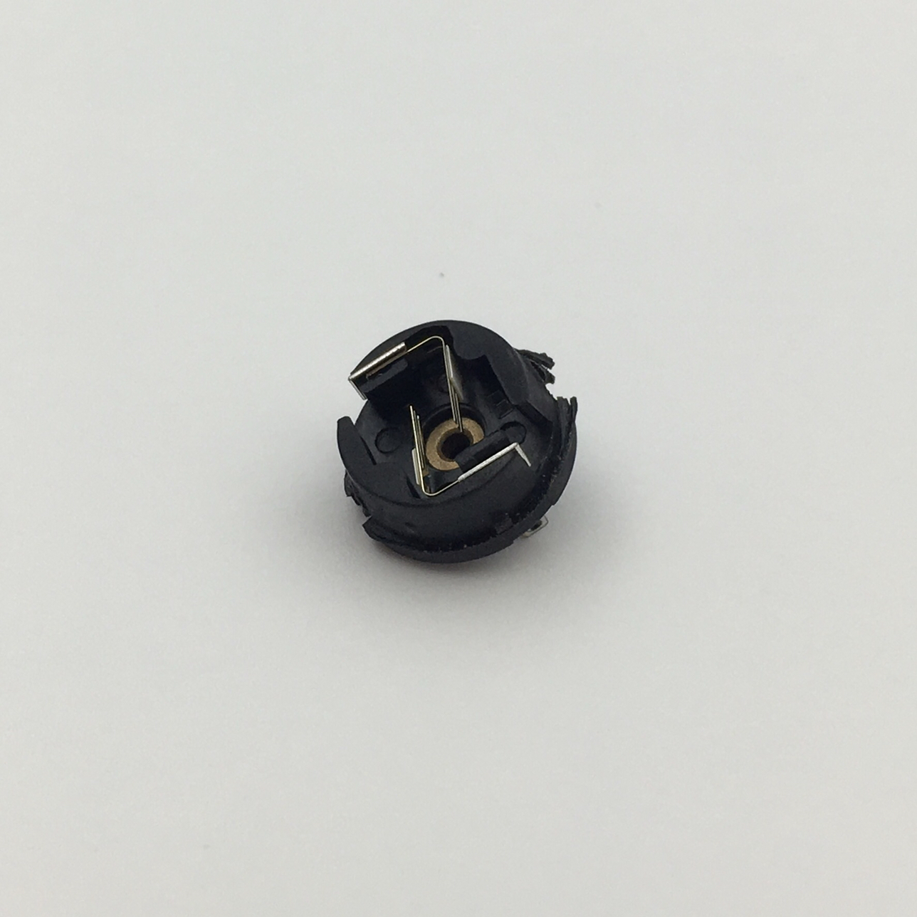
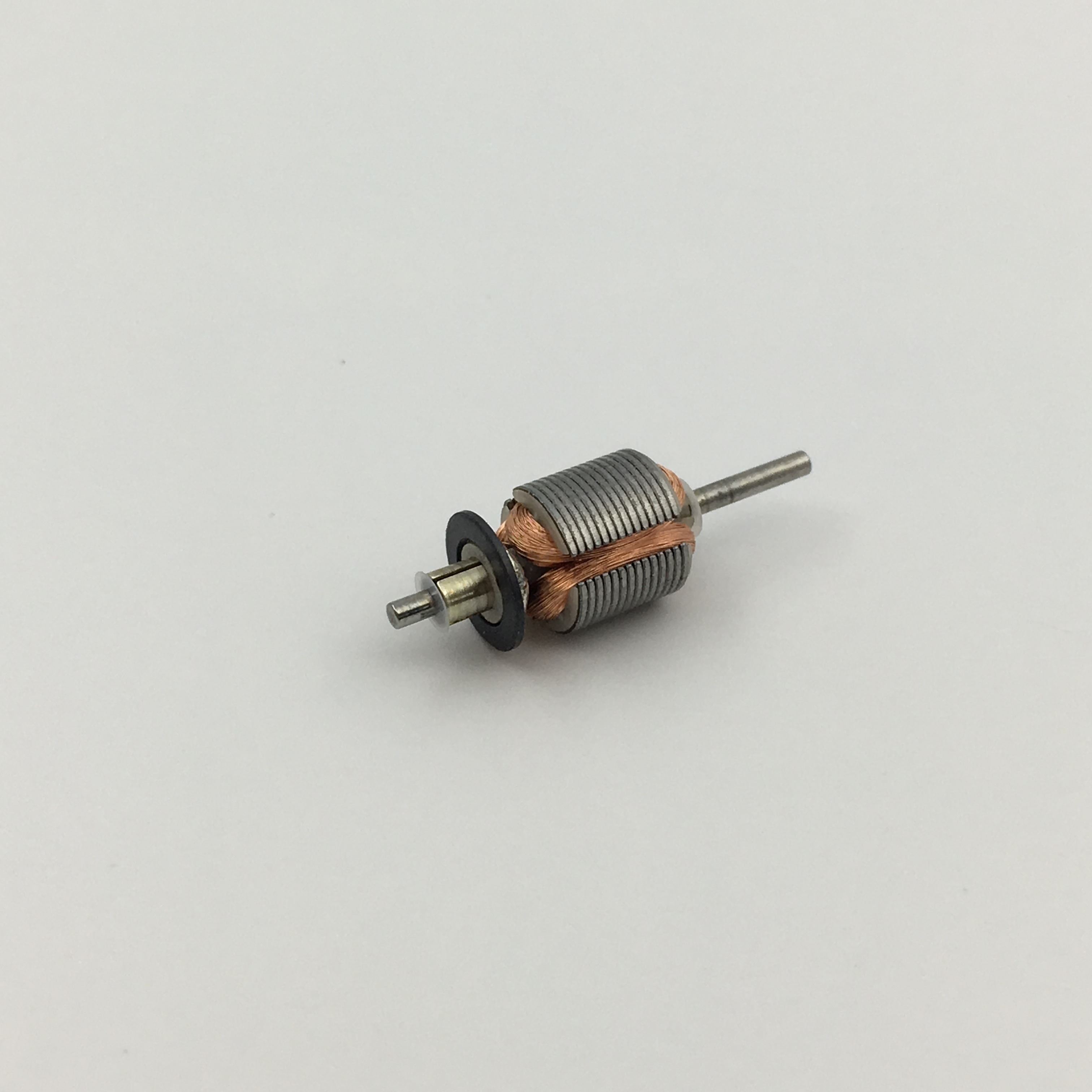
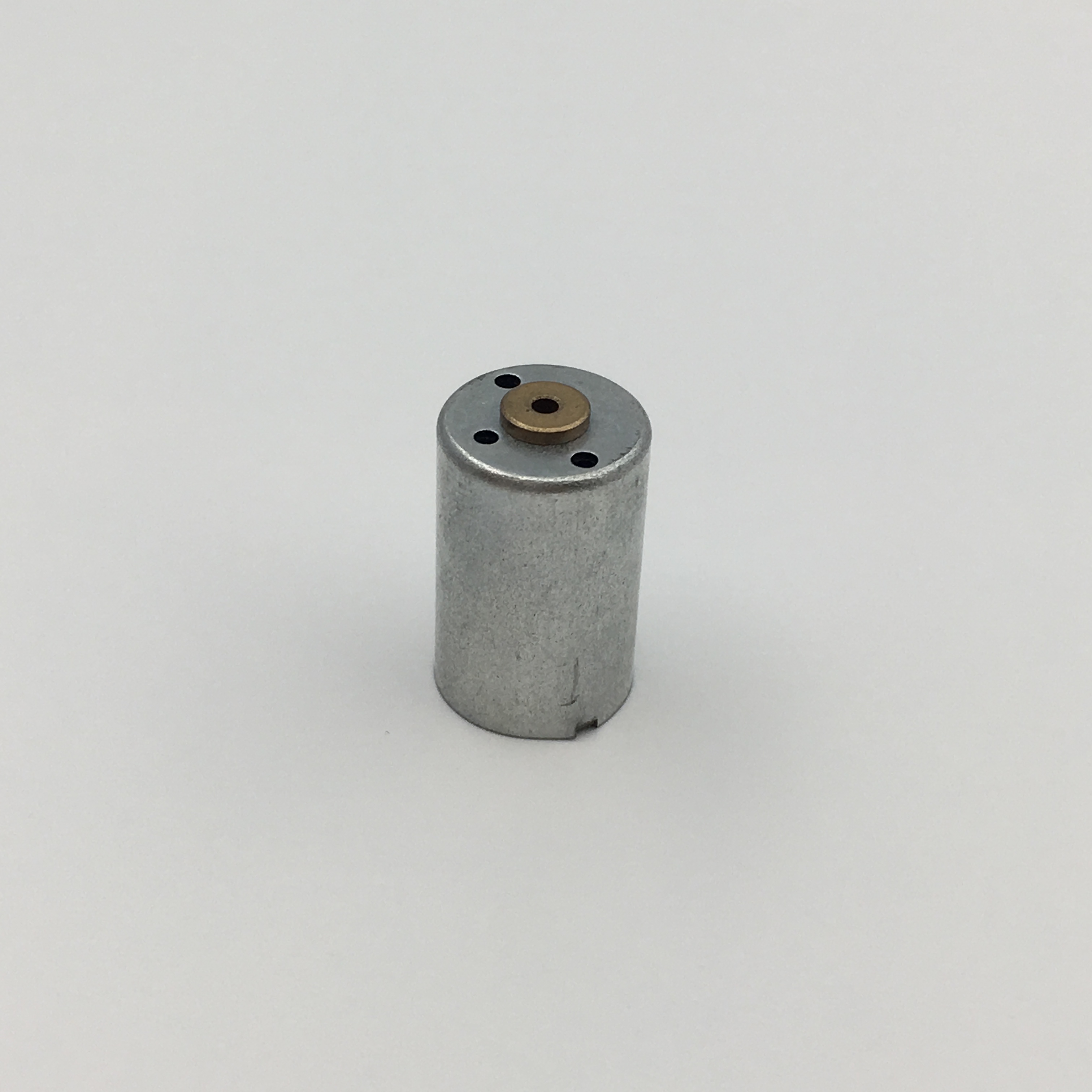
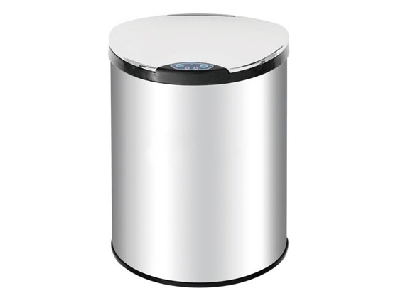
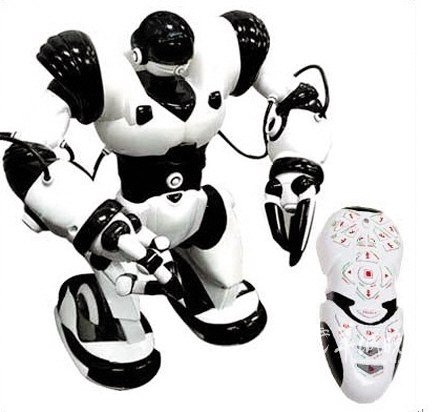
Micro motor is mainly used in: outdoor lamps, electronic toys, model aircraft, intelligent bin, breeze machine, etc

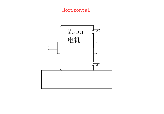
Method of use: the best stable in horizontal plane, installed on the Micro motor output shaft parts, cannot use a hammer to knock, knock prone to press into the micro motor drive, may cause damage to internal components, and cannot be used in the case of blocked.
Operating temperature range:
Micro motor should be used at a temperature of -10~60℃.
The figures stated in the catalog specifications are based on use at ordinary room temperature catalog specifications re based on use at ordinary room temperature (approximately20~25℃.
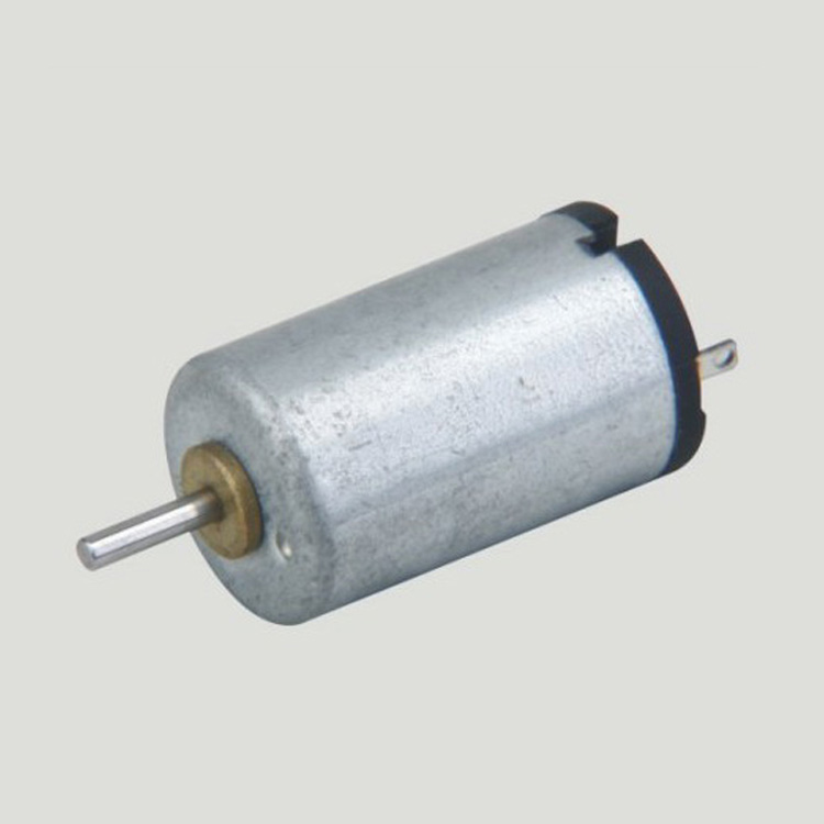
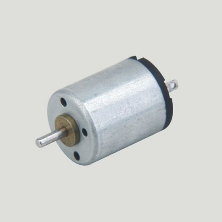
If a micro motor is used outside the prescribed temperature range,the grease on the gearhead area will become unable to function normally and the motor will become unable to start.Depending on the temperature conditions ,it may be possible to deal with them by changing the grease of the motor's parts.Please feel free to consult with us about this.
Storage temperature range:
Micro motor should be stored ta a temperature of -15~65℃.
In case of storage outside this range,the grease on the gearhead area will become unable to function normally and the motor will become unable to start.
Service life:
The longevity of micro motor is greatly affected by the load conditions , the mode of operation,the environment of use ,etc.Therefore,it is necessary to check the conditions under which the product will actually be used .The following conditions will have a negative effect on longevity.Please consult with us should any of them apply.
â—Use with a load that exceeds the rated torque
â—Frequent starting
â—Momentary reversals of turning direction
â—Impact loads
â—Long-term continuous operation
â—Forced turning using the output shaft
â—Use in which the permitted overhang load or the permitted thrust load is exceeded
â—A pulse drive ,e.g.,a short break,counter electromotive force,PWM control
â—Use of a voltage that is nonstandard as regards the rated voltage
â—Use outside the prescribed temperature or relative-humidity range,or in a special environment.
â—Please consult with us about these or any other conditions of use that may apply,so that we can be sure that you select the most appropriate model.
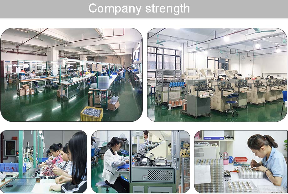
when it come to volume production,we're a major player as well .each month,we rurn out 600000 units,all of which are compliant with the rohs directive.Have any questions or special needed, please contact us, we have the engineer group and best sales department to service to you Looking forward to your inquiry. Welcome to our factory.
Micro Motor,Micro Dc Motor,Micro Vibration Motor,Micro Electrical Motor
Shenzhen Shunchang Motor Co., LTD. , https://www.scgearmotor.com