Aiming at the deficiencies of the existing mechanical wear monitoring methods, a design scheme of an on-line oil abrasive particle monitoring system based on optical methods is proposed, which realizes the detection of internal wear of gearboxes or hydraulic equipment in complex environments, and improves the detection of wear particles. Range, reducing the cost of online wear monitoring; a design scheme of image acquisition processor is proposed, which realizes the acquisition, processing and transmission of high-definition area scan camera images. The hardware circuit of the image acquisition processor is designed with Freescale's I.MX6Q as the core. In the embedded Linux environment, the software of the image acquisition processor is designed based on OpenCV to realize the processing of the images acquired by the area array camera. Experiments show that the image acquisition processor can realize online wear particle image acquisition, processing and wireless transmission functions, and can be used for oil detection, fault prediction and diagnosis in harsh working environments.
0 Preface
Abrasion is the most common form and cause of malfunctions that cause various mechanical equipment to work abnormally and fail [1]. According to a large number of statistical results, nearly 80% of mechanical failures are caused by equipment wear and lubrication failure. The oil in the lubrication system and hydraulic system is like human blood. It contains rich equipment working condition information. The abrasive particles suspended in it can reflect the degree of internal wear of the mechanical system to the maximum extent, which can provide valuable for equipment failure and maintenance as needed. Based on, eliminate potential safety hazards, and avoid major production safety accidents on site. Therefore, the detection of abrasive particles in oil is very important [2].
Wear particle detection can realize different detection methods based on different working principles such as optics, electricity and magnetic field theory, but traditional detection methods have many shortcomings. For example, spectroscopy can only measure abrasive particles smaller than 10 μm, and the equipment is generally expensive; particle counting The method needs to be calibrated after a period of use, and the cost of calibration is relatively high; the magnetic plug method is not effective for non-magnetic materials; the ferrograph method that is used more in engineering depends too much on the naked eye of the tester, and it is easy to cause judgment due to subjective judgment and visual fatigue Error: Although the inductance method can be used in online mode, it can generally only detect larger abrasive particles with a size greater than 100 μm [3]. However, the size of the abrasive particles that can characterize the severe wear failure of the mechanical friction pair is generally small, only about 10 μm [4]. In recent years, such as the literature [5], although many methods for detecting wear particles based on other working principles have been proposed, but because they all use computers or industrial computers and other sensors, they are not only costly, but also bulky, and they can only be obtained. The number and size of abrasive particles, the shape of abrasive particles cannot be obtained, and the type cannot be determined, and the products are mostly used for laboratory testing. In remote, small, and harsh industrial sites such as fan testing, real-time online monitoring cannot be achieved. Obtaining the change trend of the quantity and size of abrasive grains in time, it is difficult to make timely and accurate judgments on the working conditions.
In order to solve the deficiencies of the above detection methods, this paper proposes an on-line monitoring method for oil abrasive particles based on optical methods. This method uses embedded technology, image processing and data wireless transmission technology, uses Contex-A9 as the core IMX6Q as the hardware platform, relies on the vision library OpenCV, and uses the SIM800C wireless module to upload data remotely to complete the online monitoring of oil abrasive particles, thereby It compensates for the inconvenience caused by the insufficient detection size range and the detection time lag in the complex industrial field environment of the traditional oil wear particle detection method, so that the early warning can be made in time according to the trend of sharp increase in abrasive particles.
1 The overall structure of the system
As shown in Figure 1, the system consists of three subsystems: oil sample and optical path, image acquisition and processing, and data transmission.
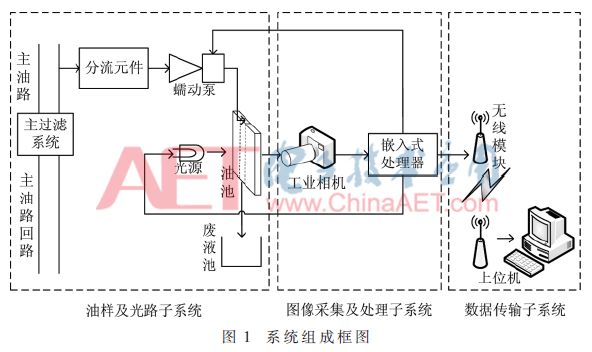
The oil sample and optical path subsystem of the oil wear particle image monitoring system is responsible for branching the oil sample from the main oil path for the image acquisition equipment to collect. Under the control of the main control chip, the main oil path in front of the main oil filter system flows into the precision oil pool through the shunt element and the peristaltic pump. Use the backlight to illuminate and project the shape of the abrasive particles onto the CMOS array of the next subsystem.
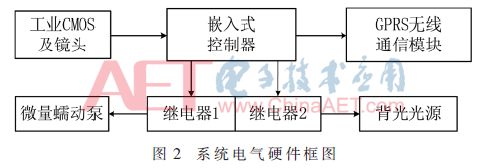
In the image acquisition and processing subsystem, an ARM-based processor is used to further control the start of the peristaltic pump through a program control relay, thereby controlling the collection of oil samples; the abrasive particles irradiated by the backlight are magnified by the macro imaging lens and then imaged to the CMOS Above, the collected images are sent to the image collection and processing subsystem through the USB2.0 data line; the collected images are processed through the program to obtain many characteristic quantities of the abrasive particles in the oil.
In the data transmission subsystem, the wireless module communicates with the ARM through the serial port, and wirelessly sends the abrasive grain characteristics collected by the ARM to the upper computer, and receives, tabulates and displays the working status of the equipment reflected by the oil on the upper computer. When necessary, alarms such as oil change, shutdown and overhaul will be issued.
2 System hardware composition
The system hardware circuit block diagram is shown in Figure 2, which is mainly composed of the main control chip, industrial lens and camera, relay and wireless communication module.
2.1 The block diagram of the image processing hardware circuit
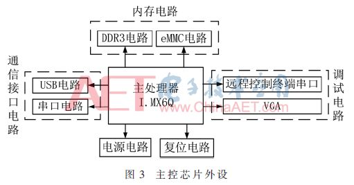
The image acquisition processor is composed of a main processor, a communication interface circuit, a memory circuit, and a debugging circuit. Its block diagram is shown in Figure 3. The DDR3 circuit is used for data calculation, and the eMMC circuit is used for data storage; the communication interface circuit connects the main processor with external cameras and wireless modules through USB and serial ports to realize the communication between the main processor and external devices; the debugging circuit is used for software The display of the programming and debugging stage. The I.MX6Q chip of Freescale is selected as the main processor chip of the image acquisition processor. Its on-chip resources are rich and the main frequency is high, which meets the requirements of embedded image processing.
2.2 Block diagram of data communication hardware circuit
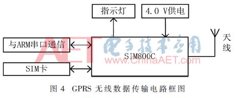
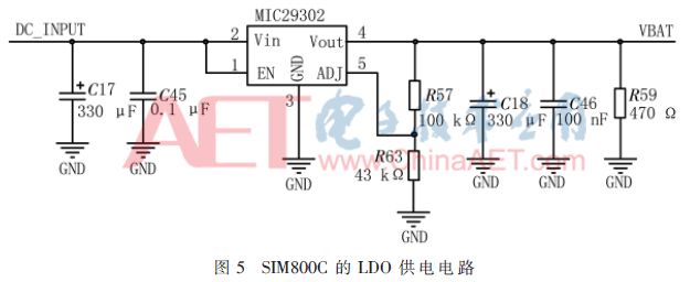
The wireless transmission block diagram of the data is shown as in Fig. 4. Among them, the GPRS wireless communication module chooses SIMCOM's industrial-grade four-band SIM800C for remote data transmission. The chip is small in size and low in power consumption, and can accurately realize data wireless transmission. The chip current peak value can reach 2 A in an instant. To ensure the stable operation of the wireless communication module, the input voltage must be stabilized at 4.0 V. Its LDO power supply circuit is shown as in Fig. 5.
3 System software design
The system software is mainly composed of image processing program, GPRS communication program and host computer display.
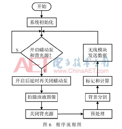
The embedded oil wear particle detection program is based on the vision library OpenCV, and the running environment is the embedded operating system of ARM-Linux. It finally realizes the automatic collection and processing of oil wear particle images and wireless upload of characteristic quantities. After the system is initialized, it is judged whether to turn on the peristaltic pump and the backlight immediately. When it is judged as N, continue to wait, when it is judged as Y, turn on the relay to turn on the peristaltic pump and the backlight light source, so that the oil is collected on-line from the main oil circuit. In the same way, after a delay, the relay will be turned off when the oil is filled with oil. The industrial camera collects the oil image and transmits it to the ARM end, completes the processing of this frame of wear image, and finally sends the data to the host computer in a wireless form. Its program flow chart is shown as in Fig. 6.
3.1 Computer Vision Library OpenCV
OpenCV is a cross-platform computer vision library that is promoted and developed by Intel Corporation and has a mature and reliable algorithm that can run on Windows/Linux/Mac operating systems [6]. By installing the corresponding cross-compiler, the source code package and dependent library are configured and compiled to realize the transplantation of the vision library. Considering the operating stability of the system, the version selected in this article is OpenCV2.4.8.
3.2 Wear particle image collection and processing
The oil sample with the wear particle information is projected onto the CMOS under the action of the backlight, and the V4L2 video kernel driver on Linux is used to realize the acquisition of the oil wear particle image.
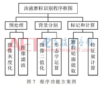
After the image acquisition is completed, the embedded hardware platform with ARM as the core realizes the preprocessing, background segmentation and feature calculation of the wear particle image. Its program function scheme is shown as in Fig. 7.
3.2.1 Image filtering
The average filtering algorithm is simple and fast, but it will cause the image to be blurred, and can only reduce the noise but cannot effectively filter the noise. Gaussian filtering is used to eliminate Gaussian noise, but it will still blur the image. Try to make the field of view bright and uniform when shooting, which can effectively reduce the generation of Gaussian noise. The median filter is selected according to the actual situation of the oil wear particle image. The basic idea is to use the median value in a certain neighborhood of a certain pixel to replace the original value, which can not only eliminate isolated noise points, but also preserve edge details to the greatest extent .
3.2.2 Binarization
In order to accurately separate the abrasive particles from the oil background, it is necessary to binarize the preprocessed image before contour extraction to separate the target and the background. The usual method is to select a fixed threshold T. Because the target object in the oil abrasive grains has a smaller gray value than the oil background, the gray value of the pixel larger than T can be set to 255, and the pixel smaller than T can be grayed The degree value is set to 0. However, this threshold needs to be determined subjectively, and it is easy to mistakenly divide the target object into the background.
The OTSU (Otsu method) threshold segmentation algorithm can automatically determine the threshold. The basic idea is to divide the image into two parts, the target and the background, according to the maximum distance between classes according to the gray characteristics of the image [7]. This article uses the OTSU algorithm.
3.2.3 Morphological operation denoising
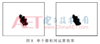
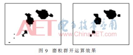
After the image is binarized, there will be slight defects on the edges of the abrasive grains, and even tiny voids inside the abrasive grains. By performing morphological opening operations on the binary image, not only can the single-pixel level noise be eliminated, but also The target abrasive particles can be separated at the delicate points; the morphological closed operation of the binary map can eliminate the small holes in the abrasive particles caused by the binarization. The two morphological operations can smooth the binary image without changing the shape and area of ​​the abrasive grains. The calculation effect is shown in Figure 8 and Figure 9.
3.3 Wireless communication
The image data of the wear particles after the ARM processing is sent to the host computer to complete the drawing table and fault warning using the wireless module. Use TCP/IP protocol and AT command to realize reliable data transmission.
3.4 PC software
The upper computer adopts the QT compilation interface to realize the statistical processing of the data uploaded by the embedded platform.
4 Experimental verification
After completing the embedded hardware debugging and Windows system-side program debugging, the program code is cross-compiled to generate an executable file that can run on ARM-Linux, and then the executable file is burned to ARM for embedded platform Image detection of wear particles.
In the experiment, a 5 million pixel camera was used to take a frame of 2 592×1 944, a color .bmp format oil copper particle image. After comparing the processed images and feature quantities, it was found that the ARM end and the PC end have the same processing effect. The processing effect is shown in Figure 10 and Figure 11. The program running time before software optimization is shown in Table 1. Some of its characteristic quantities are shown in Table 2.
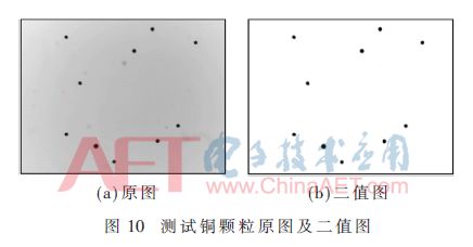
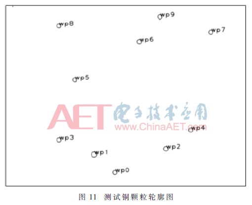

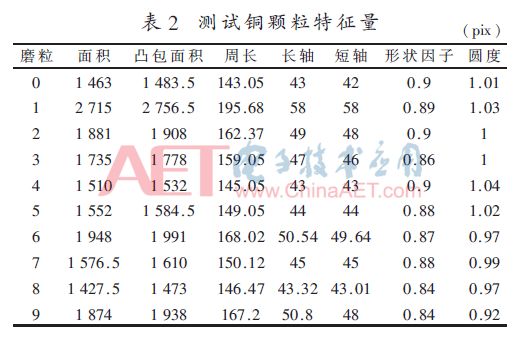
According to multiple tests on the image of small abrasive particles, it is found that the number of abrasive particles larger than 5 μm can be counted, and the function of statistics of the contour and characteristic quantity of abrasive particles larger than 20 μm can be realized. This range meets the requirements of industrial sites.
5 Conclusion
According to the above hardware system, the circuit is built and the software program is programmed. It is verified by experiments that the system can realize the detection of oil abrasive particles based on the optical method, and can obtain the basic characteristic quantity of abrasive particles in the oil stably, quickly and accurately, which is the basis for the future. This type of feature provides basic preparation for the realization of wear particle classification based on machine learning.
Reloj Inteligente
Reloj Inteligente
everyone enjoys luck , https://www.eeluckwatch.com