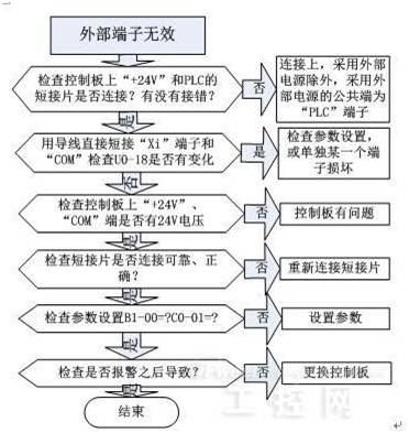
1. Is the shorting tab between the “+24V†and “PLC†terminals connected? Is there a misalignment connection (connected to another terminal)?
2. Short-circuit X1--X7 and COM terminals with one wire, check the parameters of U0-18, and whether the corresponding terminal input has action;

If only one terminal does not change, it can be judged that this terminal is damaged, and other terminals can be used for debugging.
3. Check if there is 24VDC between the "+24V" and "COM" terminals. With the multimeter DC gear, there should be 24V voltage. If the voltage between "+24V" and "COM" is normal, perform the following checks again, otherwise you can basically judge that there is a problem on the control board;
4. Is the shorting tab between the “+24V†and “PLC†terminals tightened? If the shorting piece is dropped or not tightened, the X1--X7 terminal will be invalid. Especially when the external "+24V" power supply of the inverter is used, be sure to tighten all the two screws, because the shorting piece is connected to the two. For the terminal, only one terminal is tightened, the shorting piece will not fall off, but the "+24V" terminal and the "PLC" terminal may not be connected, and the X1--X7 terminal input will also be invalid.
5. If the above detection is correct, the terminal does not run, you need to check the parameter settings. Are the parameters B1-00=1, C0-01=3 set correctly?
Note: The old version of the software (B12 and previous versions), after the inverter reported a fault, and reset, the terminal is short-circuited, the inverter will not run, the terminal needs to be removed, reconnected (there is a rising edge signal) ) will run again; the new version of the software (B13 version) defaults to the old version of the software function, but can be set by parameters (C0-21 = 1), after the fault is reset, if the terminal running command is shorted, it will run directly. Please use this function with caution to avoid danger.
The processing flow chart is as follows:
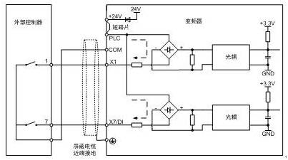
1. Dry contact wiring mode, using internal power supply ("+24V" and "PLC" shorting tabs must be connected reliably to supply power to the multi-function input terminal):
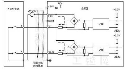
2, dry contact wiring, using external power supply ("+24V" and "PLC" shorting must be removed, the external power supply "+", connected to the "PLC" terminal, after the external contact, then access X" terminal):
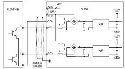
1. Connection method of open collector NPN:
A. Open circuit collector NPN wiring mode, using internal power supply (due to the internal power supply, the "+24V" and "PLC" shorting tabs must be connected reliably, and the current flow is from "+24V" to "PLC" Go to the internal control circuit of the control board, go to the “Xi†terminal, and return to the “COM†terminal of the inverter after the external contact):
B. The wiring mode of the open collector NPN is external power supply (due to the use of external power supply, the shorting tabs of "+24V" and "PLC" must be removed, and the current flow direction is from "+" to "PLC" of the external power supply. "To the internal control circuit of the control board, go to the "Xi" terminal, and return to the "0V" terminal of the external power supply after the external contact):
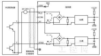
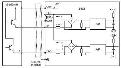
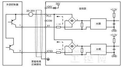
2. Wiring method of open collector PNP:
A. Open wiring collector PNP wiring mode, using internal power supply (due to the internal power supply, and the current flow direction from "+24V" to the external contact, return to the "Xi" terminal, after the control board rectifier circuit returns to " PLC" terminal, so the shorting tabs of the "+24V" and "PLC" terminals of the inverter need to be removed, and the "PLC" terminal and the "COM" terminal are shorted together):
B. Open circuit collector PNP wiring mode, using external power supply (due to the use of external power supply, and the current flow direction is from the external power supply "+", through the external contact, back to the "Xi" terminal of the inverter, through the control panel The internal rectifier circuit returns to the "PLC" terminal, so the "+" of the external power supply is connected to the external contact, and the "-" of the external power supply is connected to the "PLC" terminal of the inverter, and the "+24V" of the inverter itself is " PLC" shorting tab must be removed):
Note: All these contacts, no matter how they are connected, need to consider whether the circuit can form a loop?
Can the current flow flow according to the difference between "NPN" and "PNP"?
Third, the wiring of the inverter multi-function output terminal1. Wiring of open collector Y1, Y2:

a) use internal power supply
b) use an external power supply
Remarks:
A, the choice of pull-up resistor: need to be selected according to the power supply capacity, our internal "+24V" power supply capacity is 200mA, so the pull-up resistor is a minimum of 120 ohms, generally 2K or so, but as a PLC pulse input, need Match according to the impedance of the PLC input terminal;
B. Judging whether the multi-function input terminal is good or bad: in the case of non-conduction, there is no voltage between “+24V†and “Y1†and “Y2â€, and “+24V†and “Y1†in the case of conduction. There is 24V between "Y2".
2. Relay output wiring:

a) use internal power supply
b) use an external power supply
Note: Please note that the "+" and "-" of the relay coil cannot be reversed.
2.54mm Ejector Header Connector
Shenzhen CGE Electronic Co.,Ltd , https://www.cgeconnector.com