Overview:
In this paper, a new low-ripple high-voltage DC power supply circuit structure is proposed. The power supply adopts the principle of complementary voltage, and two half-bridge inverter circuits with the same independent output voltage and phase difference of 90° are connected in parallel and output. The output voltages are connected in parallel to achieve the purpose of reducing the ripple of the DC output voltage. Based on the introduction of the working principle and control mode of the power supply, a small power prototype was developed according to the scheme. The feasibility of the scheme was verified by combining the experimental waveforms.
High-voltage DC power supplies have been widely used in industrial, medical, nuclear, and other fields. For X-ray machines, particle accelerators, electron beam welders, electron beam exposure machines and other applications, the voltage level is relatively high, they all require low ripple voltage. In [5], several circuit topologies for high-voltage DC power supplies are introduced and compared, and their advantages and disadvantages are pointed out.
In recent years, with the application of new power electronic devices, high-voltage DC power supplies have new features such as high frequency, high efficiency, high power density, and high reliability. High frequency can improve power supply performance, reduce transformer bulk and ripple factor, but also brings new technical problems. Too high a frequency will cause the switching tube to break frequently, and the switching loss will increase, which will affect the life of the switching tube and reduce the efficiency of the whole machine.
In view of the above problems, this paper uses a dual-supply parallel output method to obtain low ripple DC. Today, when the frequency of the switching transistor is limited, the method can obtain low ripple DC at a low frequency.
(Please read the PDF for details)
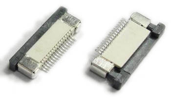
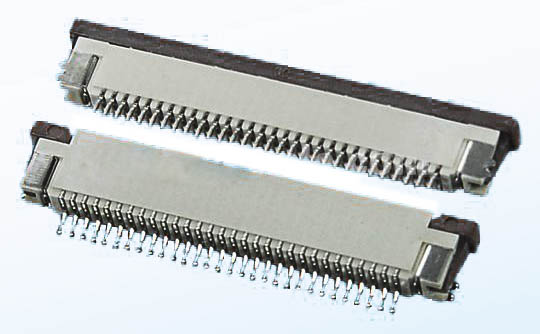
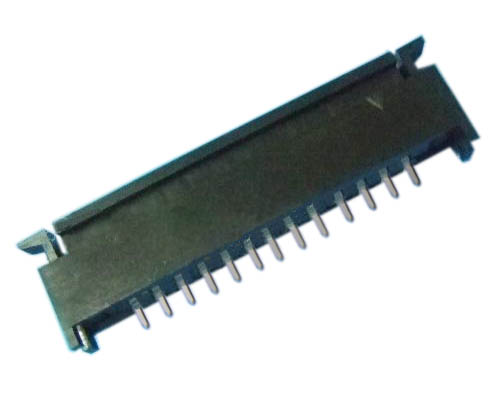
1.ANTENK Flexible Printed Circuit (FPC) and Flexible Flat Cable (FFC) connectors are ZIF (zero insertion force) and LIF (low insertion force) connectors designed to provide a fast, easy, reliable method to make a connection of flexible printed circuits to a PCB. Adam Tech`s special contact design completely preserves conductor integrity by eliminating all wiping action while making connection. Flex circuitry enters the connector and the connector cap is pressed down to capture the flex circuit producing a stable, high pressure connection. Raising the cap releases the pressure for exchange or replacement of circuitry. This series includes single and dual row versions in thru-hole or SMT mounting in vertical or horizontal orientations.
2.Our products are widely used in electronic equipments,such as monitors ,electronic instruments,computer motherboards,program-controlled switchboards,LED,digital cameras,MP4 players,a variety of removable storage disks,cordless telephones,walkie-talkies,mobile phones,digital home appliances and electronic toys,high-speed train,aviation,communication station,Military and so on


FFC Connector Range Available as:
0.3,0.5, 0.8, 1.0,1.25, 2.54mm connector pitch
Surface mount
Side and Top entry
Side entry parts - Top and bottom contact options
ZIF (Zero Insertion Force)
Slide and flip lock actuator styles
Specifications:
Material And Finish:
Insulator: LCP
Lock: PPS
Insert Spring:Phosphor Bronze,
Matte Tin Plated
Solder Platten Area:Phosphor
Bronze,Matte Tin Plated
Voltage:500 V AC(rms)/DC
Current:0.5 A AC(rms)/DC
Contact Resistance:20 mΩ max(initial)
Insulation Resistance:800 MΩ min
Operating Temp:-20°-85°
Fpc Connector,Fpc Cable Connectors,Ffc Cable Connectors,Pitch Fpc Connector,Surface mount FPC/FFC Connectors,Top entry FFC Connectors, Side entry FFC Connectors
ShenZhen Antenk Electronics Co,Ltd , https://www.antenkcon.com