Foreword: This paper mainly introduces the design of the motor drive circuit. The circuit realized by this scheme can use independent MCU or CPLD plus FET drive circuit and current sampling feedback circuit.
First, in the design of the motor drive circuit, the main considerations are as follows:Function: Is the motor unidirectional or bidirectional? Need to adjust speed? For one-way motor drive, just use a high-power triode or FET or relay to directly drive the motor. When the motor needs to rotate in both directions, you can use an H-bridge circuit consisting of 4 power components or use a double-pole double Throw the relay. If you do not need speed regulation, just use the relay; but if you need speed regulation, you can use PWM (pulse width modulation) speed regulation by using switching elements such as triode and FET.
Performance: For the PWM drive motor drive circuit, the main performance indicators are as follows.
1) Output current and voltage range, which determines how much power the circuit can drive.
2) Efficiency, high efficiency not only means saving power, but also reducing the heating of the drive circuit. To improve the efficiency of the circuit, it is possible to ensure the switching state of the power device and prevent common-state conduction (a problem that may occur in the H-bridge or push-pull circuit, that is, the two power devices are simultaneously turned on to short-circuit the power supply).
3) The effect on the control input. The power circuit should have good signal isolation at its input to prevent high voltage and high current from entering the main control circuit, which can be isolated with high input impedance or optocoupler.
4) The impact on the power supply. Common-state conduction can cause a transient drop in the power supply voltage to cause high-frequency power supply contamination; large currents can cause the ground potential to float.
5) Reliability. The motor drive circuit should be as close as possible, no matter what kind of control signal, what kind of passive load, the circuit is safe.
Second, triode-resistor for gate drive
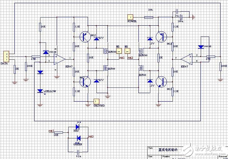
1. Input and level shifting sections:
The input signal line is introduced by DATA, the 1 pin is the ground line, and the rest is the signal line. Note that 1 foot to ground is connected to a 2K ohm resistor. When the driver board and the microcontroller are powered separately, this resistor can provide a path for the signal current to flow back. When the driver board and the microcontroller share a set of power supplies, this resistor can prevent large currents from flowing along the wires that flow into the ground of the microcontroller board. In other words, it is equivalent to separating the ground line of the driver board from the ground line of the microcontroller to achieve "one-point grounding".
The high-speed op amp KF347 (also available as TL084) acts as a comparator that compares the input logic signal to a 2.7V reference voltage from the indicator and a diode and converts it into a square wave signal that is close to the power supply voltage amplitude. The input voltage range of the KF347 cannot be close to the negative supply voltage, otherwise an error will occur. Therefore, a diode that prevents the voltage range from overflowing is added to the input of the op amp. One of the two resistors at the input is used to limit current, and one is used to pull the input low when the input is left floating.
The LM339 or any other open-circuit comparator cannot be used in place of the op amp, because the high-level output impedance of the open-circuit output is above 1 kΩ, and the voltage drop is large, and the transistor of the latter stage cannot be turned off.
2. Gate drive section:
The circuit composed of the rear transistor and the resistor and the Zener tube further amplifies the signal, drives the gate of the FET and uses the gate capacitance of the FET itself (about 1000pF) to delay the FET of the upper and lower arms of the H-bridge. Simultaneous conduction ("common state conduction") causes a short circuit in the power supply.
When the output of the op amp is low (about 1V to 2V, it can't reach zero completely), the lower transistor is turned off and the FET is turned on. The upper transistor is turned on, the FET is turned off, and the output is high. When the output of the op amp is high (approximately VCC-(1V to 2V) and cannot fully reach VCC), the lower transistor is turned on and the FET is turned off. The upper transistor is turned off, the FET is turned on, and the output is low.
The above analysis is static. The following is a discussion of the dynamic process of switching: the on-resistance of the triode is much less than 2 kΩ, so the charge on the gate capacitance of the FET can be quickly released when the transistor is switched from off to on. Closed quickly. However, it takes a certain time for the transistor to be charged by a 2 kΩ resistor when the transistor is switched from on to off. Correspondingly, the FET switches from on to off at a faster rate than from off to on. If the switching action of the two triodes occurs at the same time, this circuit can make the FETs of the upper and lower arms break and then pass, eliminating the common-state conduction phenomenon.
In fact, the output voltage of the op amp needs to change for a certain period of time. During this time, the output voltage of the op amp is in the middle between the positive and negative supply voltages. At this time, the two transistors are turned on at the same time, and the FET is turned off at the same time. So the actual circuit is safer than this ideal situation.
A 12V Zener diode for the FET gate is used to prevent FET gate overvoltage breakdown. The voltage resistance of the general FET gate is 18V or 20V, and the voltage directly applied to 24V will break down. Therefore, this Zener diode cannot be replaced by a normal diode, but it can be replaced by a resistor of 2 kΩ. 12V partial pressure.
3. Field effect transistor output section:
In the high-power FET, there is a diode connected in reverse parallel between the source and the drain. When connected to the H-bridge, it is equivalent to four diodes used to eliminate the voltage spike in the output terminal. Therefore, there is no external diode. Parallel connection of a small capacitor (between out1 and out2) at the output has certain advantages in reducing the peak voltage generated by the motor. However, there is a side effect of peak current when using PWM, so the capacity should not be too large. This capacitor can be omitted when using a low power motor. If you add this capacitor, you must use a high withstand voltage, ordinary ceramic capacitors may break through the short circuit.
A circuit consisting of a resistor and a light-emitting diode and a capacitor connected in parallel at the output end indicates the direction of rotation of the motor.
4. Performance:
The power supply voltage is 15~30 V, and the maximum continuous output current is 5A/per motor. It can reach 10A in short time (10 seconds) and 30KHz in PWM frequency (usually 1 to 10KHz). The circuit board contains four logic independent units, and the output terminals are connected to form an H-bridge power amplification unit, which can be directly controlled by a single-chip microcomputer. Realize the bidirectional rotation and speed regulation of the motor.
5. wiring:
The high-current circuit should be as short and thick as possible, and try to avoid passing through the via hole. If it is necessary to pass the via hole, make the via hole larger ("1mm) and make a small via hole on the pad. Solder fills up, otherwise it may blow. In addition, if a Zener diode is used, the source of the FET should be as short and thick as possible for the power supply and the ground. Otherwise, at high current, the voltage drop across the conductor may pass through the positively biased regulator and The turned-on transistor burns it. In the initial design, the source of the NMOS transistor was once connected to a 0.15 ohm resistor to detect the current. This resistor became the chief culprit in the continuous burning of the board. Of course, if you replace the voltage regulator with a resistor, there is no such problem.
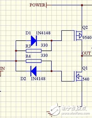
Third, the simple gate drive of the low voltage drive circuitThe maximum gate-source voltage of a typical power FET is about 20V, so in a 24V application, the gate-source voltage must not exceed 20V, which increases the complexity of the circuit. But in applications with 12V or lower, the circuit can be greatly simplified.

The left picture shows one side of a 12V transaxle, and the triode part of the upper circuit is replaced by two diodes and two resistors. (Note that the logic in the above diagram is reversed.) Due to the presence of the gate capacitance of the FET, charging the gate capacitor through R3 and R4 causes the FET to delay conduction; and directly discharges the gate capacitance through the diode to cause field effect. The tube is immediately cut off, thus avoiding common state conduction.
Fourth, L298N motor drive circuit1. Analysis of working principle:
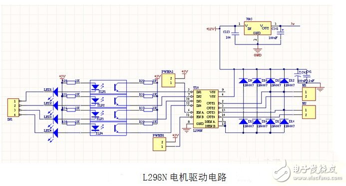
In the stepping motor drive module, TLP521 with optocoupler isolation and strong anti-interference ability is adopted as the isolated current protection chip, wherein the 17th leg of L297 controls the forward and reverse of the stepping motor by giving high and low level, and 18 feet For the stepping clock input terminal, control the time increment of each step, the half-step or the whole step of the 19-step stepping motor is selected, and the 10-pin is the enabling control terminal to control the start and stop of the motor, and the inner contains 4 Channel logic drive circuit, high voltage, high current double H bridge driver L298 to control the motor's forward and reverse; use L298 to realize motor drive and its forward and reverse, and use diode for freewheel protection, use 7805 to provide 5v power supply to controller And l298 chip power supply, this circuit is prone to heat in the case of long working hours, resulting in circuit instability.

The main features are:
Key chip: L298N double H bridge DC / stepper motor driver chip
L298N chip working voltage: DC 4.5~5.5V.
Motor drive power supply voltage DC 5--35V.
LED indicator is indicated when the power input is normal.
PCB size: 4.4*5.0cm
The maximum output current is 2A (instantaneous peak current 3A) and the maximum output power is 25W.
When the output is normal, the motor is running with an LED indicator.
With diode freewheel protection.
Two DC motors or one two-phase 4-wire (or 6-wire) stepper motor can be controlled separately.
A DC motor up to 3A can be controlled by a parallel connection method.
The motor can be reversed.
2. Implementation of analog circuit PWM

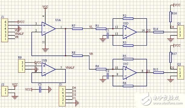
The picture above shows a PWM generation circuit that controls the two chassis drive motors using a linear joystick (or linear Hall element) on the joystick or RC joystick. J1 is the socket of the handle, and 123 and 456 are potentiometers in both x and y directions. U1B provides a half supply voltage and U1A is a voltage follower. The x, y component is synthesized into a voltage signal that controls the speed of the two motors of the left and right wheels. In use, let L = (x+1) y / (x + 1.4), R = (x-1) y / (x - 0.6), after testing has a good effect (the number is only the unit, not the voltage value) . The Schmitt oscillator consisting of U1C and U1D converts the voltage into a corresponding PWM signal for controlling the power drive circuit. Taking U1D as an example, R1 and R2 form a Schmidt circuit with hysteresis. The upper and lower thresholds are affected by the input voltage, and C1 and R3 form a delay loop. The pulse width of the oscillation is controlled by the input voltage. Q1, Q2 are triodes that form an inverter that provides differential control signals. See the analysis of the 555 oscillator for specific oscillations.
Best Selling Promotional Price 1600 DPI Wired Gaming Mouse For Computer For Apple Laptop
2. The ergonomic shape design plus scroll wheel with rubber and skin-friendly surface provide you the most comfortable feeling in hand for long time.
3. Easy and quick to use, no need to install extra drivers or software. Support USB: 2.0/3.0 port.
Gaming Mouse,Usb Wired Computer Mouse Game,Usb Wired Gaming,Wireless Mouse For Computers
MICROBITS TECHNOLOGY LIMITED , https://www.hkmicrobits.com