A safe way to detect objects is to make physical contact with the object. Contact may be the most common form of object detection and is usually achieved with a simple switch. Here, we will introduce some of the contact methods, including the "soft touch" technology, robots using this technology can be detected through subtle contact.
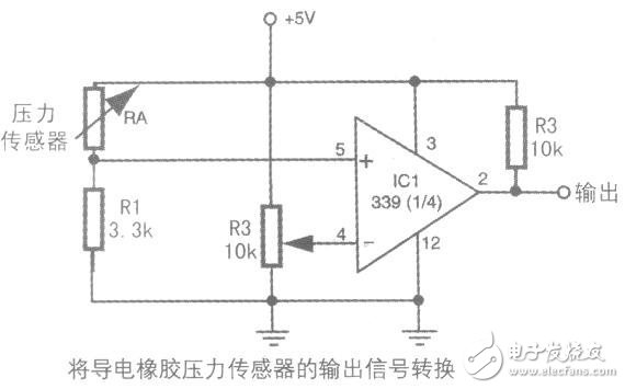
A more reasonable interface circuit using a conductive rubber sheet is given in the figure below. A conductive rubber sheet and a 3.3k resistor are connected in series to form a voltage divider between the ground and the positive voltage of the power supply. When the conductive rubber sheet is pressed, the voltage at the output of the sensor changes. The output of the sensor is the point between the piezoelectric piece and the resistor, which is connected to the inverting input pin of the comparator 339. When the voltage of the piezoelectric piece exceeds the reference voltage of the comparator, the output state of the comparator changes, indicating that a collision has occurred. The output of this comparator can be used to drive a relay that controls the direction of the motor or directly to a microprocessor or computer port.

Multi-channel collision switch
What happens when there are many switches or proximity detection devices placed around the robot? I had to connect the output of each switch to the computer, but that wasted a lot of peripheral ports. A better solution is to use a priority encoder or multiplexer. These two schemes allow multiple switches to be connected on a common control line. The robot's microprocessor or computer will query this control line instead of each switch or proximity detection device.
Use priority encoder circuit design
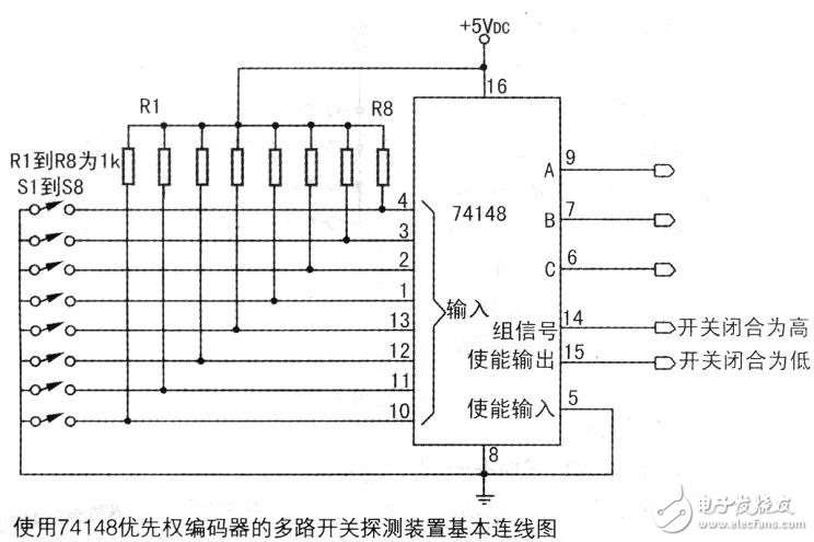
The circuit in the figure below uses a 74148 priority encoder manifold.

The inputs to the manifolds are the outputs of those switches. When a switch is closed, the corresponding binary code appears at the ABC output pin. For the priority encoder, only the highest value of the switch can be displayed on the output. In other words, if switches 4 and 7 are both closed, the output can only react to pin 4 closure.
Use resistor divider
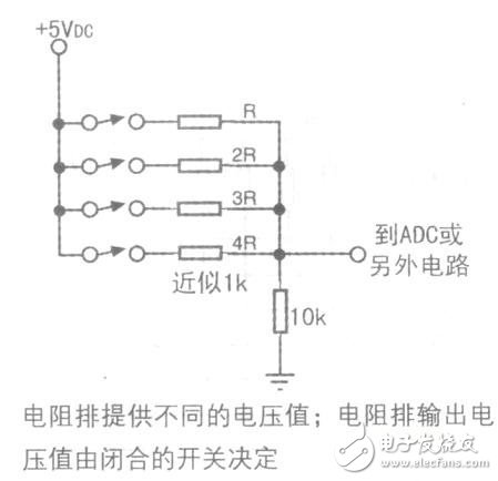
If the robot's computer or microcontroller has an analog-to-digital converter (ADC) or one can be added, the multiplexer interface can be implemented in another technique: a resistor divider. The concept is very simple, as shown in Figure 18. Each switch is grounded through one end of a resistor, and the +V voltage is connected in series with another resistor to each switch. Multiple switches are connected in parallel to the input of the ADC as shown. These resistors form a voltage divider. Since each resistor value is different, when a switch is closed, the corresponding voltage value is unique. Note that since the resistors are connected in parallel, there may be multiple switches closed at a time. Thereby getting an intermediate value. Explore the resistance values ​​connected to each switch for maximum flexibility.

yucheng county huibang electric technology ltd , https://www.hbspeaker.com