In the communication system, due to the wide antenna beam of the communication ground station, affected by many factors such as ground objects, landforms and sea conditions, the receiver receives electromagnetic waves that arrive through several paths such as refraction, reflection and direct reflection. Multipath effect. The electromagnetic wave rays arriving by these different paths are inconsistent and time-varying, resulting in the fading state of the received signals; these electromagnetic wave rays arrive at different delays, which in turn leads to inter-symbol interference. If the multi-ray intensity is large and the delay difference cannot be ignored, a bit error will be generated. This error cannot be eliminated by increasing the transmission power, and the fading caused by the multipath effect is called multipath fading, which is also generated. The source of intersymbol interference. For digital communications, radar best detection, etc. will have a very serious impact.
Causes of multipath fading
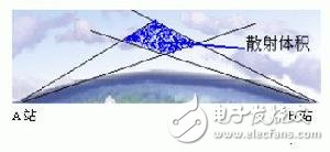
Tropospheric scattering propagation path
Radio wave propagation for mobile communications includes direct waves, diffracted waves, scattered waves, and reflected waves. When there are only direct waves and one reflected wave, if the reflected wave path changes, the path difference changes, and the phase of the two signals at the receiving point changes. In terrestrial mobile communication systems, mobile stations often work in urban buildings and other complex terrain. Due to the low height of the mobile station antenna, most of the time is "submerged" below the height of the urban building, there is no line of sight at all. Therefore, the radio wave propagation between the base station and the mobile station has almost no direct wave form, but a reflected signal of a plurality of paths appears, so that the signal arriving at the receiving antenna is a composite wave of each electric wave from a different propagation path.

Propagation path of short-wave signal reflected from the ionosphere
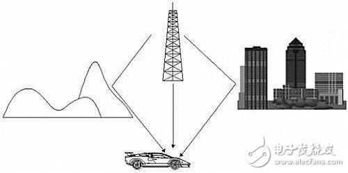
Due to the different propagation paths, the properties of the reflectors are different, so that the amplitude and phase of each reflected wave arriving at the receiving point are random. There may be a direct wave and a plurality of reflected waves of different paths. The field strengths at different positions in a small range may be added in the same phase and become larger, and sometimes reversed to cancel and become smaller, forming a standing wave distribution. In the mobile communication environment, even if the surrounding environment is unchanged, the rapid movement of the mobile station in the standing wave field causes the amplitude of the composite wave received by the receiving antenna to change rapidly and in a wide range. This forms a multipath fast fading phenomenon of the signal received by the receiver. For different bands and different modes of propagation, the mechanism for forming multipath propagation is not the same. The drawings illustrate the principles of short-wave ionospheric reflection channels and multipath fading in ultrashort wave, microwave troposcatter channels and mobile communications.

Mobile communication path
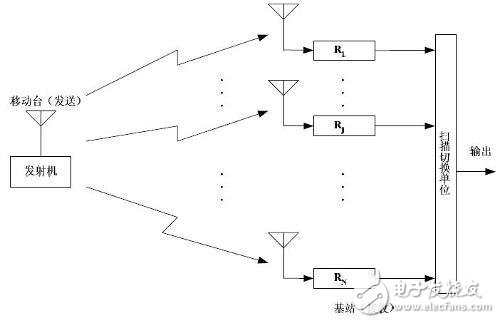
1, diversity reception
As a kind of multiplicative interference, fading seriously affects the performance of communication systems, so corresponding measures must be taken to overcome them. The more effective anti-fading measures are: diversity reception is to synthesize several composite signals with different fading conditions (relatively statistically independent) at the receiving end, and then combine them in a certain way to make the signal noise of the total received signals. The ratio is reduced and the effect of fading is reduced. This is an effective method for overcoming the effects of fading in a long history and widely used. Available diversity methods are: spatial diversity, frequency diversity, angular diversity, polarization diversity, time diversity, and so on.

2, signal design
The so-called signal design is to design a signal with strong anti-fading capability for the channel, and adopt the corresponding modulation and detection technology at the end of the transmission. Such as multi-ary signal, time-frequency phase modulation technology and time-frequency modulation signal, pseudo-noise coding (pseudo-random coding) and other spread spectrum communication technology.
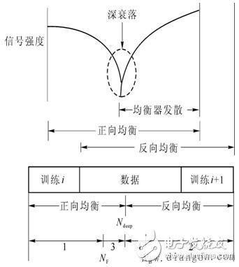
3. Adaptive communication technology
The main adaptive equalization technique is to adjust the receiver parameters according to the influence of the channel on the signal to offset the above effects. For example, in a medium-capacity system of digital microwave communication, the frequency characteristics of the channel are often compensated by a frequency domain adaptive equalizer. In the large-capacity system, in addition to the frequency domain equalizer, a time-domain adaptive equalizer that compensates the waveform is also used, and the effect is remarkable.

1.0mm (.039″) Pitch Pin Headers
Overview
Antenk offers a variety of high quality and competitively priced 1.0mm pitch single, dual, three, quad row pin (male) headers used in many board-to-board PCB connections, fitting small-sized, densely-packed devices.
This low-profile component is made from high-temperature thermoplastic and is offered with several means of connections and mounting styles such as through-hole (THM) or surface mount (SMT) and can be in vertical (straight), elevated or at a right angle configuration/orientation dissipating current of about 1.0 A or less.
The pin (male) header is generally mated with receptacle or stackable header connectors (female sockets). This types of pin headers are suitable for PCB board to board connection or for signal transmission application.
Applications of 1.0mm Pitch Pin Headers
Its small size is most suitable for PCB connections of small equipment and devices such as WiFi equipment, gaming consoles, measurement instruments, and other equipment in need of a special interface to become interconnected
Mount Type: Through-hole vs Surface Mount
At one side of this pin header is a series of pins which can either be mounted and soldered directly onto the surface of the PCB (SMT) or placed into drilled holes on the PCB (THM).
Through-Hole (Poke-In)
Best used for high-reliability products that require stronger connections between layers.
Aerospace and military products are most likely to require this type of mounting as these products experience extreme accelerations, collisions, or high temperatures.
Useful in test and prototyping applications that sometimes require manual adjustments and replacements.
1.0mm vertical single row header, 1.0mm vertical dual row header, 1.0mm Elevated single row pin header, 1.0mm Elevated dual row pin Header, 1.0mm Right-angle single row header and 1.0mm Right-angle dual row header are some examples of Antenk products with through-hole mount type.
Surface-Mount
The most common electronic hardware requirements are SMT.
Essential in PCB design and manufacturing, having improved the quality and performance of PCBs overall.
Cost of processing and handling is reduced.
SMT components can be mounted on both side of the board.
Ability to fit a high number of small components on a PCB has allowed for much denser, higher performing, and smaller PCBs.
1.0mm Right-angle Dual Row pin header, 1.0mm SMT Single row pin header, 1.0mm SMT Dual row pin header and 1.0mm Elevated Dual Row Pin Header are Antenk`s SMT pin headers.
Soldering Temperature for 1.0mm Pitch Pin Headers
Soldering SMT pin header can be done at a maximum peak temperature of 260°C for maximum 60 seconds.
Pin-Type: Vertical (Straight) and Right-Angle
1.0mm pitch headers may be further classified into pin orientation as well, such as vertical or straight male header or right-angle male header.
Vertical or Straight Pin (Male) Header Orientation
One side of the series of pins is connected to PCB board in which the pins can be at a right-angle to the PCB surface (usually called "straight" or [vertical") or.
Right-Angle Pin (Male) Header Orientation
Parallel to the board's surface (referred to as "right-angle" pins).
Each of these pin-types have different applications that fit with their specific configuration.
PCB Connector Stacking
Elevated Pin Header Orientation
Elevated pins aka Stacked Pins or Mezzanine are simply stacked pin headers providing an exact distance requirement between PCBs that optimizes electrical reliability and performance between PCB boards.
Profile Above PCB
This type of configuration is the most common way of connecting board-to-board by a connector. First, the stacking height is calculated from one board to another and measured from the printed circuit board face to its highest insulator point above the PCB.
Single, Dual or Multiple Number of Rows
For a 1.0mm straight or vertical male pin header, the standard number of rows that Antenk offers ranges from 1 to 2 rows. However, customization can be available if 3 ,4 or n number of rows is needed by the customer. Also, the number of contacts for the single row is about 2-50 pins while for dual row, the number contacts may vary from 4-100 pins.
Pin Material
The pins of the connector have been designed with copper alloy. With customer`s demand the pins can be made gold plated.
Breakaway design
The pin headers are also equipped with a breakaway design making them fully compatible with their female receptacles.
Custom 1.0mm Pitch Pin Headers
Customizable 1.0 mm pitch pin headers are also available, making your manufacturing process way faster as the pins are already inserted in the headers, insulator height is made at the right size and the accurate pin length you require is followed.
Parts are made using semi-automated manufacturing processes that ensure both precision and delicacy in handling the headers before packaging on tape and reel.
The tape and reel carrier strip ensures that the headers are packaged within accurately sized cavities for its height, width and depth, securing the headers from the environment and maintaining consistent position during transportation.
Antenk also offer a range of custom Tape and reel carrier strip packaging cavities.
Male Header Pins,1.0Mm Male Header,1.0Mm Pin Header,1.0Mm Male Header Pins, 1.0mm THM Male Header, 1.0mm SMT Male Header
ShenZhen Antenk Electronics Co,Ltd , https://www.antenkelec.com