introduction
This article refers to the address: http://
In 1915, Ford Motor Company used electric lights and electronic horns for its T-type cars. Since then, the car's reliance on electrical and electronic systems has increased. The initial system is often local and independent, for example, a switch that controls the headlights is directly connected to the battery. But today - these systems are connected to each other. When the headlights are turned on, the dashboard lighting, mirrors, and other systems may all go into new working conditions. In order to achieve these functions, various systems must communicate with each other. With the development of automotive technology, cars have many networks that make this communication possible. Due to the continuous development of self-driving cars, there is an increasing demand for data transmission between the interior of the car and between cars. This article introduces you to three automotive communication standards—Controller Area Network (CAN), Ethernet, and Flat Panel Display Link (FPD-Link), and explores the most suitable system for each type of interface.
CAN bus
The CAN bus was originally developed by Robert Bosch GmbH in the 1980s. Today, it is supported by many integrated circuit and subsystem manufacturers and is used in all modern cars. The CAN bus allows messages transmitted over the bus to communicate with different controllers or processors on the bus. It uses a prioritized sub-sequence method so that low-priority messages do not interfere with high-priority messages. The CAN bus has a transmission rate of less than 1 Mbps and the message length (CAN frame) is typically 50 to 100 bits.
Since many different controllers can share a single CAN bus, it is generally not well suited for sending messages that require more than 100 updates per second. Ideally, it is suitable for relaying slower status updates, from sensors to engine control units. It includes applications related to other mechanical systems (transmission, braking, cruise fixed speed control, power steering, window, door locks, etc.) with limited data and often relatively low bandwidth.
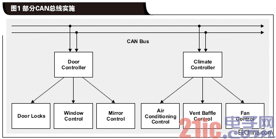
As more and more sensors and processors continue to be added to the network, the total transmission speed is further reduced and the automotive system becomes more complex. Figure 1 shows the CAN bus used to implement the door and temperature control functions. Since all of these are low bandwidth applications, mutual interference is not a big issue. However, if the same bus has to handle higher bandwidth, such as more important functions such as engine control, the priority of the door and temperature control needs to be set low enough so that these functions do not interfere with engine control.

The end result is that the CAN bus is also suitable as a communication network between automotive mechanical sensors and systems, but it is difficult to achieve high bandwidth requirements for applications such as entertainment systems or cameras or radar sensors.
Ethernet
Ethernet is one of the most common high-speed interfaces in our homes and offices, and some cars transmit a variety of high-speed data over Ethernet. Like the CAN bus, Ethernet is a packetized packet system in which information between nodes on each part of the network is transmitted in packets. Like the CAN bus, Ethernet is a two-way network. As the number of system nodes increases, the transmission speed of all individual links decreases. However, the link speed of Ethernet transmission data is 100 times that of the CAN bus.
Ethernet is suitable for medium-bandwidth communication in applications such as navigation systems and controls. It can be used as a CAN bus in the same way, while providing more bandwidth. Ethernet is a rational choice for replacing the CAN bus, but because the cost per node of Ethernet is high, it may not replace the CAN bus, but it will complement the CAN bus.
Today, some cars are using Ethernet to meet big data transmission requirements, such as tail-end cameras and entertainment systems. A special mention of automotive applications is Texas Instruments' (TI) DP83848Q-Q1. It is an Ethernet PHY (classified as AEC-Q100 Level 2) and includes a loop test for auxiliary system diagnostics.
To transmit video over an Ethernet network, even if there is only one video channel being transmitted, the video must be compressed at its source and then decompressed at the destination to avoid exceeding the Ethernet bandwidth limit. For applications such as the rear camera, it means that there is a relatively high-power processor inside the camera to fully compress the image so that it can be transmitted over Ethernet. That is to say, the camera is physically larger, more costly, and consumes more power than a solution that does not require more image compression. Another drawback of this solution is that video compression and decompression increase the latency of the link. If the same Ethernet is shared by several cameras or other video-sources in the car, a compromise and balance between the amount of compression (and the corresponding video quality) and the number of supported video channels is required. The use of a hierarchical structure to establish multiple networks within the car can alleviate this problem. - One network handles only engine control and diagnostics, the second network handles the rear entertainment and audio systems, and the other handles driver assistance features such as line-of-sight enhanced cameras. Finally, Ethernet has more power than the CAN bus at the expense of higher complexity and is still difficult to handle for the highest bandwidth applications (eg video, etc.). -
FPD link
The FPD link is a technology developed for point-to-point transmission of high-bandwidth data. It has a very high speed (several gigabits per second) forward channel and a low speed reverse channel. The reverse channel is used to transmit I2C at 400 kbps or to control GPIO at the highest rate of 1 Mbps. The purpose of developing an FPD link is to transmit video-frequency data inside the car. For example, it can be used to transfer uncompressed video to a video display, while the reverse channel sends information from the display touchpad back to the processor that generated the video. The physical layer of the FPD link can be a twisted pair or coaxial cable. Wiring is dedicated, so if the FPD link is used for a rear camera, one cable is connected from the rear camera to the processor and the other cable is connected from the processor to the vehicle display.
An important benefit of using an FPD link in this application is that both the camera and the display can be very simple circuits because compression and decompression are not required. In addition, since the link is dedicated, the image quality of the video system is independent of other parts of the car. The reverse channel can be used to structure the camera, operate the zoom lens, or send touch screen information back to the controller without interrupting the video stream in the forward channel.
Another important factor in terms of autonomous vehicles is the amount of delay in the link. This processing is increased by the processing required to compress and decompress the image. For applications such as back-end entertainment, the delay between reading data from a DVD and displaying its content on the screen is not important. However, if the transmitted image is from a camera that shows a highway pedestrian, this delay can have dire consequences.
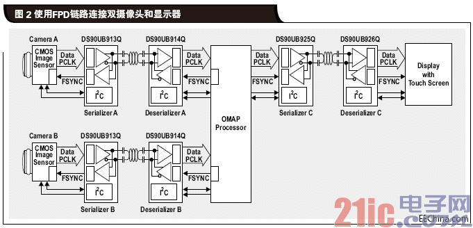
When high bandwidth and low latency are the most important considerations, the FPD link should be preferred to achieve some important connections. In addition, wiring can be made simpler because it can support reverse channels and can be powered by a single twisted pair or coaxial connection. Figure 2 shows an OMAPTM video processor that connects two different cameras and displays to connect peripherals through a single twisted pair cable. This twisted pair cable supports camera video data and touch screen/camera setup data. It also powers the display or camera. Since each link is dedicated to one peripheral device, there is no interference between the signals of the two cameras.

in conclusion
So which interface is best for car communication? They are all suitable, but they need to be determined according to the specific application. The CAN bus dominates low-speed control applications that require ever-decreasing costs. As bandwidth requirements increase, Ethernet acts as an enhanced interface to meet medium bandwidth requirements. When the highest bandwidth and lowest delay link is required, for example, a look-around camera system that provides the environment for the autopilot, the FPD link is fully compliant.
Solar Charge Controller ,Solar Controller,Solar Regulator,Solar Panel Controller
zhejiang ttn electric co.,ltd , https://www.ttnpower.com