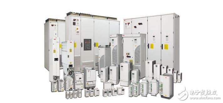
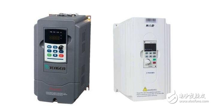
Variable-frequency drive (VFD) is a power control device that controls the AC motor by changing the working frequency of the motor by applying variable frequency technology and microelectronic technology. Generally, a device that converts an alternating current having a constant voltage and frequency into an alternating current of a variable voltage or frequency is called a "frequency converter".

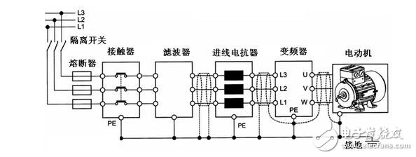
The frequency converter is a device that converts the power frequency power supply (50HZ or 60HZ) into another frequency by using the on-off function of the power semiconductor device to realize the variable speed operation of the motor, wherein the control circuit completes the control of the main circuit, and the rectifier circuit converts the alternating current Into a direct current, the DC intermediate circuit smoothes the output of the rectifier circuit, and then the inverter circuit reverses the direct current into alternating current.
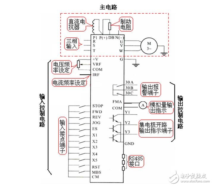
The frequency converter is mainly composed of rectification (AC to DC), filtering, re-rectification (DC to AC), braking unit, drive unit, and detection unit micro-processing unit. In order to operate normally, the inverter must have a series of control terminals on the outside. The control terminals are divided into main circuit terminals, input control terminals and output indication terminals.

The frequency converter integrates high voltage and high power transistor technology and electronic control technology and is widely used. The function of the frequency converter is to change the frequency and amplitude of the AC motor power supply, thus changing the period of the moving magnetic field to achieve the purpose of smoothly controlling the motor speed. The appearance of the frequency converter makes the complicated speed control simple. The inverter + AC squirrel cage induction motor combination replaces most of the work that can only be done with DC motor, which reduces the volume and reduces the maintenance rate. Technology has reached a new stage.

The overload must also be overcurrent. Why should the inverter separate the overcurrent and the overload? There are two main differences:
(1) Different protection objects
Overcurrent is mainly used to protect the inverter, and overload is mainly used to protect the motor. Because the capacity of the inverter sometimes needs to be increased by one or two gears than the capacity of the motor. In this case, the inverter does not have to overcurrent when the motor is overloaded.
The overload protection is carried out by the electronic thermal protection function inside the inverter. When the electronic thermal protection function is preset, the “current take-up ratio†should be accurately preset, that is, the ratio of the rated current of the motor to the rated current of the inverter:
IM%=IMN*100%I/IM
Where, IM% - current draw ratio;
IMN - rated current of the motor, A;
IN—The rated current of the inverter, A.
(2) The rate of change of current is different
Overload protection occurs during the working process of the production machine, and the rate of change of current di/dt is usually small;
Excessive currents other than overload are often sudden, and the rate of change of current di/dt tends to be large.
(3) Overload protection has inverse time characteristics
The overload protection is mainly to prevent the motor from overheating, so it has the "inverse time limit" characteristic similar to the thermal relay. That is to say, if it is less than the rated current, the operation time can be made longer, but if it is exceeded, the operation time is allowed to be shortened.
In addition, since the heat dissipation condition of the motor deteriorates when the frequency is lowered. Therefore, in the case of the same overload of 50%, the lower the frequency, the shorter the time allowed to operate.

The overcurrent trip of the inverter is divided into short circuit fault, trip during operation and tripping during the rising and falling speed.
1, short circuit fault:
(1) Fault characteristics
(a) The first trip may occur during operation, but if it is restarted after reset, it will often trip at a speed.
(b) has a large inrush current, but most inverters are already capable of protection tripping without damage. Since the protection trip is very fast, it is difficult to observe the magnitude of its current.
(2) Judgment and processing
The first step is to judge whether it is short-circuited. For easy judgment, a voltage meter can be connected to the input side before restarting after reset. When restarting, the potentiometer will slowly rotate from zero. At the same time, pay attention to the voltmeter. If the output frequency of the inverter rises immediately and it trips immediately, and the pointer of the voltmeter has an instant return to “0â€, the output of the inverter has been short-circuited or grounded.
The second step is to judge whether it is short-circuited inside the inverter or externally. At this time, the wiring of the inverter output should be disconnected, and then the potentiometer should be turned to increase the frequency. If it still trips, it indicates that the inverter is internally short-circuited. If it is no longer tripped, it means that the inverter is short-circuited externally. The line between the device and the motor, as well as the motor itself.
2, light load over current load is very light, but over current trip:
This is a phenomenon unique to variable frequency speed regulation. In the V/F control mode, there is a very prominent problem: the instability of the motor magnetic circuit system during operation. The basic reasons are:
In low-frequency operation, in order to drive a heavier load, torque compensation (ie, increasing the U/f ratio, also called torque boost) is often required. The degree of saturation of the magnetic circuit of the motor varies with the weight of the load. This overcurrent trip caused by the saturation of the magnetic circuit of the motor mainly occurs in the case of low frequency and light load. Workaround: Repeat the U/f ratio.
3. Heavy load over current:
(1) Fault phenomenon Some production machinery suddenly increases in load during operation, even “stuckâ€. The speed of the motor drops sharply due to the movement, the current increases sharply, the overload protection does not work, and the overcurrent trip occurs.
(2) Solution
(a) First understand if the machine itself is faulty, and if there is a fault, repair the machine.
(b) If this overload is a phenomenon that may occur during the production process, first consider whether the transmission ratio between the motor and the load can be increased. Appropriate increase of the transmission ratio can reduce the resistance torque on the motor shaft and avoid the situation of not moving. If the transmission ratio cannot be increased, only consider increasing the capacity of the motor and the inverter.
4. Overcurrent in speed up or down speed:
This is caused by the speed increase or the speed reduction is too fast. The measures that can be taken are as follows:
(1) Extend the rise (decrease) speed time First, understand whether to allow the extension or deceleration time to be extended according to the production process requirements. If allowed, the rise (decrease) speed time can be extended.
(2) Accurate pre-elevation (decrease) speed self-processing (anti-stall) function The inverter sets the self-processing (anti-stall) function for overcurrent during the rising and falling speeds. When the rising (lowering) current exceeds the upper limit current of the pre-turn, the rising (lowering) speed will be suspended, and when the current falls below the set value, the rising (lowering) speed is continued.
Overload trip of the frequency converter:The motor can rotate, but the operating current exceeds the rated value, called overload. The basic reflection of overload is that although the current exceeds the rated value, the magnitude of the excess is not large, and generally no large inrush current is formed.
1, the main reason for overload
(1) The mechanical load is too heavy. The main feature of the overload is that the motor is hot and can be found by reading the operating current from the display.
(2) The three-phase voltage is unbalanced, causing the operating current of a certain phase to be too large, resulting in an overload trip. The characteristic is that the motor is not heated evenly. It is not always found when reading the running current from the display screen (since the display only shows one Phase current).
(3) Malfunction, the current detection part inside the inverter is faulty, and the detected current signal is too large, causing tripping.
2, inspection method
(1) Check if the motor is hot. If the temperature rise of the motor is not high, first check whether the electronic thermal protection function of the inverter is pre-determined. If the inverter still has a margin, the electronic thermal protection function should be relaxed. Depreciation.
If the temperature rise of the motor is too high and the overload that occurs is a normal overload, it means that the load of the motor is too heavy. At this time, it is first necessary to increase the gear ratio appropriately to reduce the load on the motor shaft. If it can be increased, increase the transmission ratio. If the gear ratio cannot be increased, increase the capacity of the motor.
(2) Check whether the three-phase voltage on the motor side is balanced. If the three-phase voltage on the motor side is unbalanced, check whether the three-phase voltage at the output of the inverter is balanced. If it is not balanced, the problem is inside the inverter.
If the voltage at the output of the inverter is balanced, the problem is on the line from the inverter to the motor. Check that all the screws on the terminals are tightened. If there is a contactor or other electrical device between the inverter and the motor, Check that the terminals of the electrical appliance are tight and that the contact is in good condition.
If the three-phase voltage on the motor side is balanced, the operating frequency at the time of tripping should be known:
If the operating frequency is low and vector control (or no vector control) is used, the U/f ratio is first lowered. If the load is still driven after the reduction, the U/f ratio of the original pre-turn is too high, and the excitation current is If the peak value is too large, the current can be reduced by lowering the U/f ratio. If the load is reduced after the reduction, the capacity of the inverter should be increased. If the inverter has a vector control function, the vector control mode should be adopted.
Fork Type Connecting Terminals
Taixing Longyi Terminals Co.,Ltd. , https://www.longyicopperlugs.com